DATAPixx Trigger Output
Configure the characteristics of a digital trigger signal to be generated from a VPixx video I/O hub.
Thank you for your interest in LabMaestro! The page you are trying to access is under development. We are working on comprehensive documentation to help you make the most of our software. If you require any help, please feel free to contact us via email at support@vpixx.com.
The digital trigger command is sent via USB to the video I/O hub and executed by the device once the instructions are received. Intended use: send a message to a third-party device. Useful to send ‘messages’ to facilitate post-processing or operate a juice pump.
Mode: Selects which types of trigger to send:
“PositivePulse”: for a single square wave pulse voltage change from 0V to 5V, returning to 0V.
“NegativePulse”: single square wave pulse voltage change from 5V to 0V, returning to 5V.
Digital Output: The digital output value you want to trigger. Please note that this is not the pin number, the mapping of a pin to the digital output can be found in the respective user manual.
Duration: Defines the duration of each pulse, in milliseconds. In other words, how long will it stay at 0V or 5V before returning to its initial state.
Duty Cycle: Ratio of which the signal stays in the positive or negative state.
Repetitions: Specifies how many times the trigger pulse should be repeated, typically a single repetition.
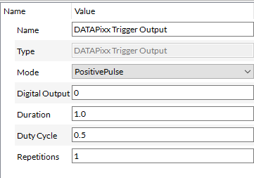
Screenshot from LabMaestro Public Beta 1.6.0
In the above screenshot, on Digital Out 0 (Pin 1), there will be a 0.5 sec (half the duration) positive trigger, bringing the value from 0 to 1 and then back to 0.