-
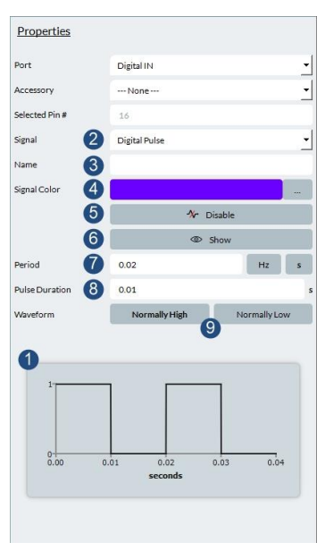
Waveform graph: this gives you a preview of the waveform as the signal is inserted.)
-
Signal: you select the digital pulse here.
-
Name: allows you to name your signal, such as “MRI trigger”, or “EEG Sync”
-
Color of the signal in the graph and the IOConfiguration.
-
Enables or disables the signal. When your signal is enabled, the global Start/Stop signal controls the state of this signal. If the signal is disabled, you can only start it with this button.
-
Show or hide this specific signal in the Signal Viewer. This is connected with the chosen signals in the graph.
-
Period (in seconds, or hertz), which is the time for a full pulse before it repeats itself.
-
Pulse duration: how long a signal stays high or low.
-
High or low determines the state of this pulse for the pulse duration.
The signal allows you to create a digital output waveform. This can be used to simulate any external equipment that would normally be sent in the digital output of a VPixx device. For example, an MRI usually sends a 2-Hz TTL trigger which can be recorded in the digital inputs and later be used to correlate timings of certain video events with the MRI scans.
This UI allows you to create multiple digital waveforms with all the parameters that would be found in normal equipment: period, pulse duration and pulse behavior. In Figure 17, the period is 0.02 second, with a pulse staying at a logical high for 0.01 second, or half of the period. This makes it such that half of the signal is logically high and the other half is logically low.
When you disable one of the signals, you will notice that the IO Configuration widget lists it as “Disabled” to indicate the current state. This means that nothing will be generated once the start signal button is pressed, until you press the enable button (#5 above).
The selected pin number relates to the pin that would be found on a real device. When using software, we usually refer to the digital inputs using their number (such as Digital Input 3). Please note that the pin numbers are not equal to the digital input numbers.