In this guide, we will cover how to present stereoscopic stimuli using the PROPixx projector and DepthQ 3D Polarizer. These two devices can be used together for full-colour stereoscopic presentation at up to 480 Hz (240 Hz/eye). In addition to high-speed presentation, this system has several other advantages, including:
-
Passive circular filters are plastic and thus MRI, MEG and OPM safe
-
Custom filter sheets can be purchased to create custom viewing apparati (e.g., for non-human primates)
-
No specialized graphics card or native 3D support required
-
Optional custom high-speed sequencer designed in partnership with the NIH to actively manage crosstalk levels, and reduce Pulfrich effects
First, we will consider some general hardware and screen requirements, then discuss our recommended method of preparing stimuli for 3D stimulus presentation. Code examples will be provided where appropriate.
Getting Started: Equipment and Materials
To effectively present 3D stimuli, the DepthQ polarizer must be connected to the VESA 3D port on the back of the PROPixx (pictured below). The polarizer should be placed directly in front of the lens with the arrow pointing away from the projector. Wingnuts on the sizes of the polarizer frame can be used to adjust the height of the polarizing filter so that it aligns with the lens.
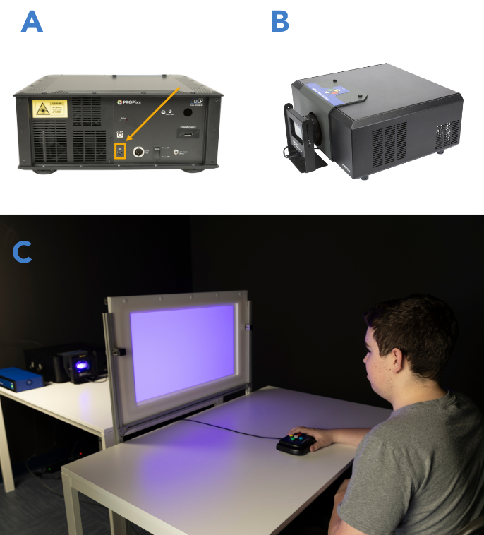
The 3D glasses provided along with the polarizer are standard circular polarizing filters. These are the same glasses used for 3D movies at a cinema. If you need a custom lens layout, you can purchase right- and left-handed circular filter material directly from certain manufacturers (for example, here) and cut it to size. Note that when buying filter material, HE indicates left-handed and HER indicates right-handed polarization.
It is normal for the polarizer and glasses to filter some visible light. Average spectral transmission of 30-35% is not uncommon. During luminance tests, VPixx staff scientists noted that inexpensive, commercial 3D filter glasses can vary in transmission rates across units. Users requiring an exact measure of light transmission should take direct measurements using a colorimeter or spectrophotometer, and should not assume measurements generalize across individual pairs of glasses.
Projection screen materials
Typical projection screens are designed for Lambertian light distribution. In other words, they aim to diffuse or reflect light in every direction, thus ensuring 1) equal luminance output across the display surface and 2) wide viewing angles. Unfortunately, this same property severely degrades 3D polarization. In practice, projection screens optimized for 2D use make for poor-quality 3D displays.
Fortunately, specialty ‘silvered’ screen materials exist. These materials prioritize direct reflectance or transmission, preserving polarized light. Silvered screens are often recognizable by their shiny surface and grey coloration (as opposed to the bright white of 2D screens). Below is a side-by-side example:
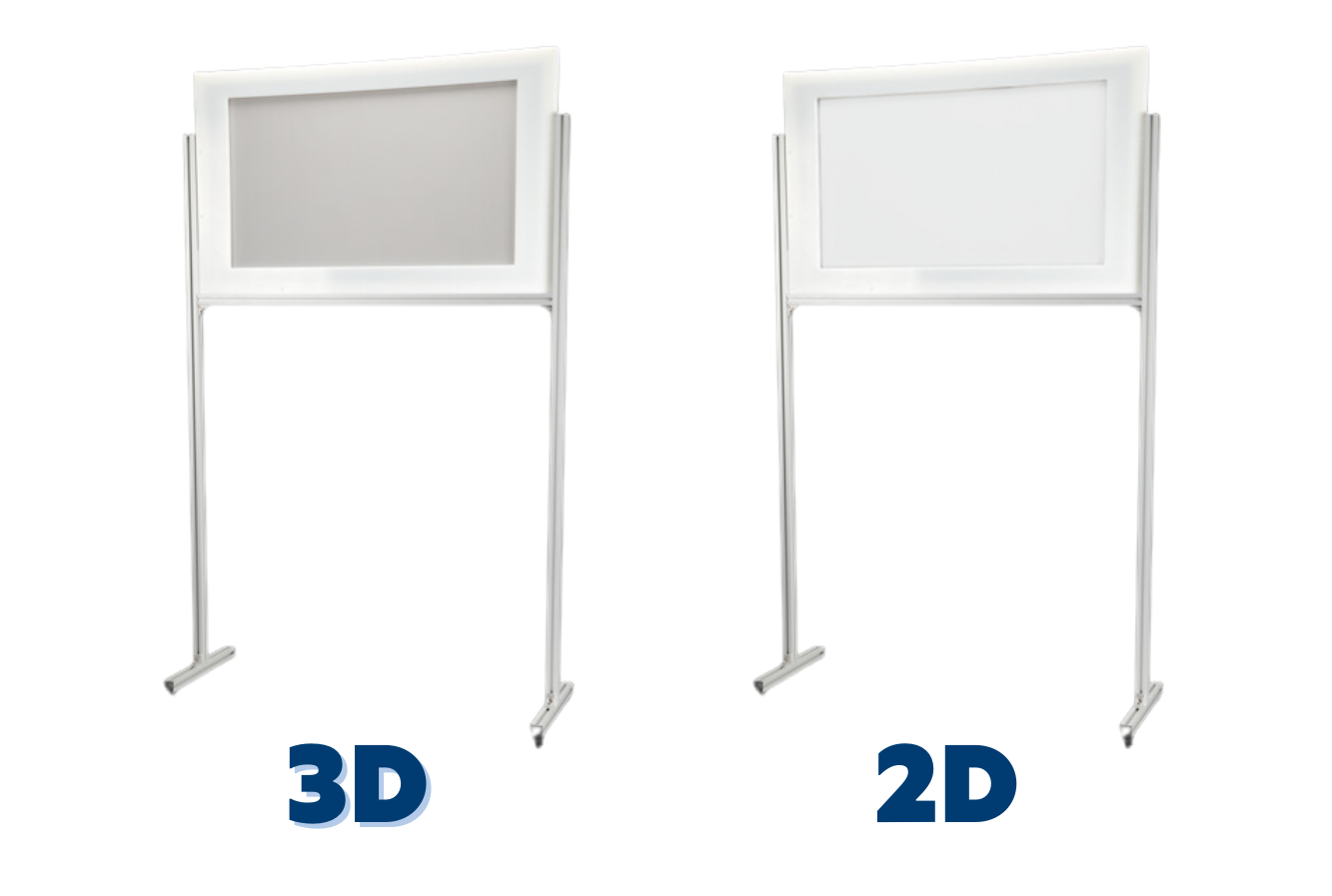
VPixx Technologies manufactures several screen shapes and sizes for standalone, tabletop and in-bore projection systems. All of our screen models can be fitted with a 3D-optimized screen material.
Due to the non-Lambertian light distribution, 3D screens are more prone to hotspotting (bright spots and uneven luminance), particularly at short projection distances. VPixx Software Tools include a PROPixx calibration routine to correct for hotspotting in these cases; see the section below for details.
If you intend to build your own screen for stereoscopic presentation, we recommend the following flexible screen materials from Stuart FilmScreen, which can be purchased directly from the supplier:
Rear-projection: Stuart FilmScreen FilmScreen 150
Front-projection: Stuart FilmScreen Silver 5D
These are the same materials we use in our screens.
Mirrors in the light path
Some projection systems use one or more 45-degree mirrors to redirect the beam of light to the screen. This is common in MEG and MRI facilities, where the projection waveguide may be offset from the screen location. MRI systems also use mirrors mounted on the head coil to allow the participant to view an image on a screen at the head of the bore.
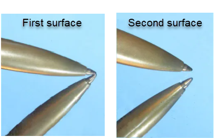
For 3D applications, we recommend all mirrors in the light path be first-surface for the best possible 3D image. That is, the reflective layer of the mirror should be in front of the glass layer, not behind it. This ensures internal reflections within the glass layer do not compromise the polarization.

An easy way to tell if a mirror is first- or second-surface is to place an item against it. If it connects with its reflection, it is a first-surface mirror.
Finally, some eye-tracking systems utilize “hot” mirrors that have an infrared reflective coating. It is strongly advised to avoid using hot mirrors during 3D stimulus presentation, as these are known to disrupt polarization.
Enabling 3D Mode and Formatting 3D Stimuli
There are many ways to format 3D stimuli for presentation. Here we discuss several strategies and when it is best to use them. All of the strategies discussed are supported by the PROPixx; some are more robust than others. At the end of this section, we provide a summary of the different options, their supported refresh rates and their best use cases.
Frame-sequential stereo
In frame-sequential stereo, images are interleaved temporally. Even and odd video frames are presented to the left and right eye, respectively.
.png?cb=05321fd6295e54d179ed9f967048f0db)
Image alternation is controlled manually (e.g., drawing left and right eye images and flipping them one after another) or via dedicated stereo draw buffers alternately sampled during stimulus presentation.
This mode is the default behaviour for a connected 3D Polarizer. It will alternate polarization on subsequent video frames until instructed otherwise, independent of video content.
This method’s biggest advantage is simplicity and ease of implementation; however, it is vulnerable to frame dropping and 3D de-synchronization. As such we recommend a small modification to this method, described in the next section.
Stereo Blue Lines
Stereo Blue Lines are a popular method of explicitly encoding each video frame to target the correct eye. This preserves stereo synchronization even if your system is dropping frames.
Stereo Blue Line is easy to implement:
-
Organize your stimuli as you would for frame-sequential stereo.
-
To assign a frame to the right eye: Set the bottom row of pixels in the frame to an intensity greater than mid-grey [128, 128, 128]
-
To assign a frame to the left eye: Set the bottom row of pixels in the frame to an intensity less than mid-grey [128, 128, 128]
Note images must be full-screen for Blue Lines to work.
.png?cb=2e88c2d024e9e8577fd65e245b75c49f)
Some software will automate Blue Line generation for you. We generally recommend drawing the line yourself. It is simple and ensures you are formatting your video frames correctly.
‘Blue line’ is the name for historical reasons; the line's colour is unimportant. As long as your pixel values are brighter than mid-grey ([128, 128, 128] in RGB255) the 3D assignment will work as intended.
Quad4x3D Mode
If you are using the Quad4x sequencer, a special command will immediately assign each quadrant to a specific eye. Simply enable the mode and ensure you assign the correct stimuli to each quadrant. This method is robust against de-synchronization by frame dropping, because if a frame is dropped all four quadrants are lost, and the next frame will show content in the correct order.
.png?cb=565a3fb28f724427dbb626a141f8ab48)
For more details on Quad4x, see our VOCAL on high-speed projection modes.
Top-Bottom Mode
Top-Bottom mode was introduced in software revision 3.9 (July 2021). In this mode, left and right images are stacked on top of one another in a single double-height image (1920 x 2160 @ 60 Hz), which the system deconstructs and presents to each eye sequentially (1920 x 1080 @ 120 Hz).
.png?cb=ca281a70b1ef77dda075060c9f30458f)
This mode was originally designed for use with 3D stimuli designed in Unity and Unreal game engines. However, it may be useful for other high-level stimulus-generation software such as PsychoPy Builder. Because this mode receives left and right eye images on the same video frame from the GPU, there is no risk of de-synchronization of 3D. Occasional frame drops are not likely to be visible.
To use Top-Bottom mode, you must configure the monitor to accept the 1920 x 2160 resolution using our LabMaestro software.
Configuring your PROPixx for Top-Bottom Mode
-
Ensure your PROPixx is connected directly to the PC by USB. It should also be connected by video cable via the PROPixx Controller or DATAPixx3.
-
Open the LabMaestro application.
-
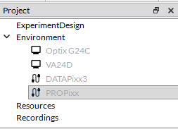
In the Project Panel on the left-hand side, find the PROPixx and double-click on it to open the Device Settings.
-
At the bottom of the Device Settings, select TopBottom3D from the list of resolutions. You will be prompted to restart the display.
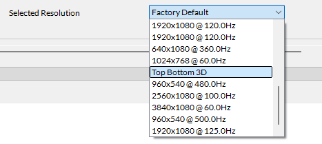
-
Change the display resolution in your operating system’s display settings, if necessary. The resolution should be set to 1920 x 2160, and the refresh rate should be 60 Hz.
-
Restart your experiment software. Some software like MATLAB only check for resolution on startup, and need to be restarted to register a new display resolution.
PsychoPy Builder example
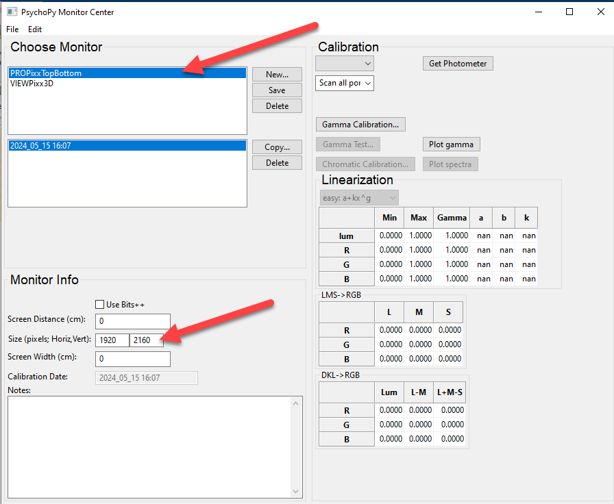
Implementing Top-Bottom mode in PsychoPy Builder is straightforward. We recommend creating a new monitor in the monitor center, to ensure the proper resolution is used. Open the Monitor center, and create a new display with the correct 1920 x 2160 resolution:
Next, when creating your stimuli, draw images and text as a single double-height image. Images and text directed at the left eye should be placed in the top half of the image, and those directed at the right eye should be placed in the bottom half.
This is a great opportunity to take advantage of PsychoPy’s normalized spatial units. For example, here is the positioning for text presented in the middle of the left eye image:
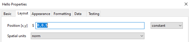
The same text, presented to the right eye, would be positioned at [0, -0.5].
Unity Example
-
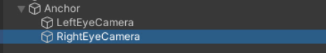
In the Scene view, create an empty GameObject named Anchor. Attach two child cameras, LeftEyeCamera and RightEyeCamera.
-
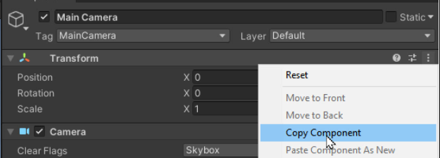
Adjust Anchor’s transform components to match that of the scene’s Main Camera. You can do this by selecting the three dots icon in the corner of the Transform component of the Main Camera, and selecting ‘Copy Component.' Select Anchor, click on the three dots in the Tranform Component, and select ‘Paste Component.’
-
Delete the Main Camera.
-
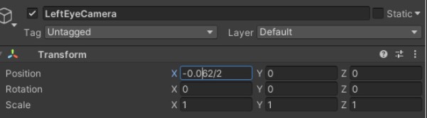
Offset the x position of both the LeftEyeCamera and RightEyeCamera by the 1/2 interpupillary distance each. You may want to write a script to adjust this dynamically for each participant.
-
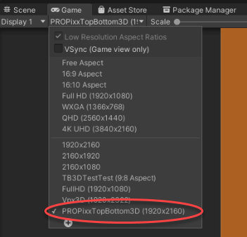
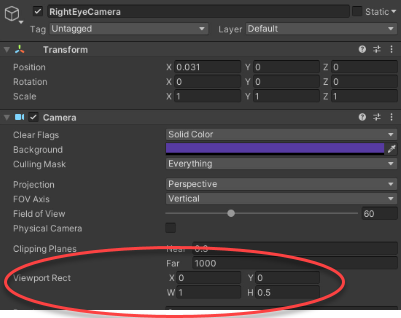
In the Game view, add a new resolution for the PROPixxTopBottom3D that is 1920 x 2160 pixels.
-
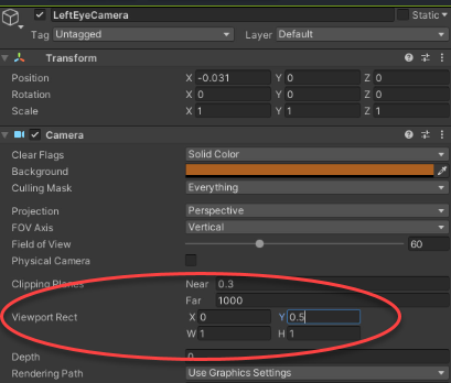
Modify LeftEyeCamera so that it renders only in the top half of the display. To do this, set the LeftEyeCamera Viewport Rect Y value to 0.5.
-
Repeat this process for RightEyeCamera and the lower half of the display. Set RightEyeCamera Viewport Rect H to 0.5.
-
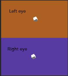
You should now have a Game view with the left and right eye perspectives stacked vertically. This video will be passed to the PROPixx and converted to alternating frame stereo presentation.
RB3D Mode
RB3D Mode is a custom PROPixx sequencer that VPixx designed in partnership with the NIH. This mode uses the red and blue colour channels to specify right and left eye images, respectively; the system converts these to greyscale images presented to the right and left eye in a single video frame via a custom subframe DLP sequencer. Each frame will show the left image at half-intensity for 1.2 ms, full intensity right image for 2.4 ms, and then the left image for another 1.2 ms at half-intensity. The rest of the frame is blank. This results in the same exposure time for both eyes, and prevents bias of which image is projected first or last.
.png?cb=94a3d752f9e041ab17215c11fe8f44da)
RB3D mode enables active crosstalk correction and eliminates Pulfrich effects.
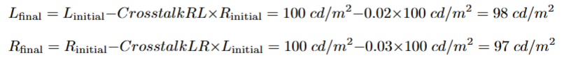
Crosstalk correction of the left eye image follows the formula:
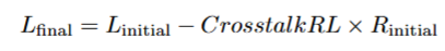
Where L (initial) is the desired left eye intensity; CrosstalkRL is the proportion that the right eye image ‘leaks’ into the left eye image (default is 0); R (initial) is the desired right eye intensity. L (final) is the left eye value required to achieve the desired left eye intensity, given the measured crosstalk levels.
Similarly, the formula for correcting the right eye is:
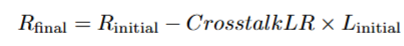
Where R (initial) is the desired right eye intensity; CrosstalkLR is the proportion that the left eye image ‘leaks’ into the right (default is 0); L (initial) is the desired left eye intensity, and R (final) is the value required to achieve the desired right eye intensity.
For example, suppose we want to present gray (100 cd/m2) to both eyes. We pass a pixel value equivalent to this intensity to the display. We then measure the left eye output at 103 cd/m2 and the right eye output at 102 cd/m2.
The PROPixx has a fully linear gamma; assuming no other image modifications are being applied by your experiment software (see this guide), we can attribute the additional 3% intensity measured in the left eye to ‘leak’ or crosstalk from the right-eye image. Similarly, the additional 2% intensity in the right eye can be attributed to the leak from the left-eye image. To correct this leakage and actively eliminate this crosstalk in our stimuli, the display adjusts the final output values such that the observed (measured) output is 100 cd/m2 for both eyes.
This transformation is fully automated with the crosstalk correction commands in our APIs. Measure the crosstalk in the left and right eyes, define these values with our API commands, and then program your stimuli as usual. The hardware will automatically correct each eye image separately on every frame. We recommend performing a few validation measurements to verify you are achieving the desired output. Make adjustments as needed.
Summary of Different 3D Modes Available with the PROPixx
|
|
Description |
Maximum Refresh |
Best Used For: |
|---|---|---|---|
|
Frame-sequential stereo |
Temporally interleave left/right eye images |
Up to 60 Hz/eye |
Simple 3D applications where no frame drops are present |
|
Frame-sequential stereo with Blue Lines |
Temporally interleave left/right eye images, blue line used to encode polarization assignment |
Up to 240 Hz/eye (in 480 Hz real-time mode) |
Any 3D application where video must be robust against frame dropping |
|
Quad4x3D |
Four quadrants of display are shown sequentially |
240 Hz/eye |
High speed displays, robust against frame dropping |
|
Top-Bottom Mode |
Left and right eye images stacked in a double-height window; shown sequentially on display |
Up to 60 Hz/eye |
3D applications where stimuli are created in Unreal or Unity game engines |
|
RB3D Mode |
Custom sequencer that presents left and right eye images as greyscale subframes |
Up to 120 Hz/eye |
Specialized applications where greyscale is appropriate and crosstalk levels are actively controlled |