Defining triggers using Pixel Mode
The Digital Output DB-25 connector on your VPixx device has 25 physical pins, numbered 1-25. With the exception of ground pin 13, each pin is capable of transmitting a low or a high voltage output. More simply, we can say that each pin can send a value of 0 (low) or 1 (high). Therefore, the Digital Output connector can theoretically send 224 unique outputs. TTL pulses or “triggers” refer to a change in this output state, signalling a new event.
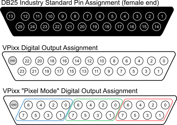
Pin assignment vs. Digital Output labeling in normal and Pixel Modes
The assignment of pin numbers 1-25 on the Digital Output DB-25 connector is based on an industry standard, and doesn’t necessarily reflect the way any device uses the pins. VPixx relabels these pins as “Digital Outputs” for programming purposes. In Pixel Mode, since we will use the colour of a pixel to select which pins we want to trigger, we break the pins into three sets of 8 for red, green and blue. For simplicity, in this guide we have labelled them 7-0.
The digital outputs correspond to the pin shown in the same position. For example, if I set Red 1 to high, I am raising the voltage on physical pin 14. It is important to keep in mind that other manufacturers may label pins differently in their own applications. DB25 pin labels can always be found in the manufacturer product manual.
Each of these pins can be in a state of 0 or 1. We can write the pattern of low and high states out from position 7 to 0, like so:
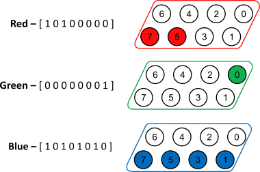
R, G and B digital input states
These states can be read as binary numbers (base 2, 0-1). If we convert these binary numbers into decimal (base 10, 0-9) we get Red 160, Green 1, and Blue 170.
To set a specific trigger for a given frame of your display, you simply need to set the colour of the top left pixel of that frame to the [R, G, B] values that correspond to your desired digital output. You can use whatever program you like to do this—MATLAB, E-Prime, or even PowerPoint. As long as you can control the colour of that top left pixel, you can use Pixel Mode. Here’s what our example looks like, with the pixel size exaggerated:
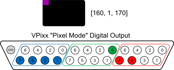
RGB pixel effects on digital output
Keep in mind that your recording system does not actually care about colour, only pin states. In order to decode the trigger as it is read by your recording system, you will need to know how your system reads the 24 TTL pins.
The important thing to remember is that your [R, G, B] values, when converted to binary, correspond to the state of the digital outputs on the DB-25—where 0 is low and 1 is high.
If you are unfamiliar with counting in binary, you can use online converters (e.g., https://codebeautify.org/decimal-binary-converter ) to convert between binary and decimal. Some software has functions to convert decimal to binary and back. MATLAB and Excel use bin2dec()and dec2bin(). Similarly, Python uses int()and bin().
Pixel value calculator
You can work out what [R, G, B] values you need to send to raise the voltage on specific pins by using binary and the parallel port/digital out assignments, as we did above. You can also use our handy calculator to figure out what values you will need to trigger specific pins:
Choosing good trigger values
Some graphics cards have a feature called dithering which can alter R, G and B values by +/- 1 after the value has been set by the user. This can inadvertently disable your triggers, and may have serious consequences for your experiment! For this reason, it is good to think carefully about what triggers you should use to signal events.
It is sometimes possible to disable dithering, but a better approach is to choose your triggers defensively. First, and easiest, is to define events by a range of codes, i.e., your desired code +/- 1.
Alternatively, you can ignore certain pins, and take care to avoid event codes which have a major impact on digital output. Consider Red “126” vs. “127” vs. “128”:
[0111 1110] = 126
[0111 1111] = 127
[1000 0000] = 128
If you are only concerned about the states of red 4, 5, and 6, then dithering will not be an issue for you if you use a value like 126 or 125; however, you will still need to avoid values on the cusp of a major change in the binary representation of the number, like 127 and 128.
Always double check your trigger output before collecting experiment data! In addition to dithering, some software can add overlays which may alter pixel values, particularly around the edges of the screen. Screen recording software in particular often does this. Other forms of pixel manipulation (e.g. blending, antialiasing, filters or gamma correction) can also affect the final pixel identity used to generate your TTL output.