Skip table of contents

Sending Triggers with Pixel Mode

In Pixel Mode, your VPixx hardware sends automated digital signals based on the colour of the top left pixel of the display. This guide explains the principles of how Pixel Mode works and how to use it in your research.

Looking for a brief overview? Check out our short video below:

https://www.youtube.com/watch?v=vho2QrYMHRw

Introduction to digital signalling

Researchers often have to align recorded data and events in their experiment timeline. For instance, researchers might ask the following questions:

  • Where in our MEG trace did our stimulus first appear onscreen?

  • When did the fixation cross appear in our eye-tracking data?

  • Where in our EEG data did the response phase begin?

To address these questions, researchers send carefully timed digital signals from their experiment to their recording system, to act as event ‘markers' in the data stream. These markers help parse and interpret a continuous stream of recorded data. Ideally, event markers should be fast, precise, automatic, and informative. They should reliably tell the researcher when something happened and should be able to carry unique information about what happened.

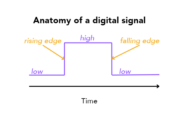
To send event markers from VPixx hardware to your recording system, we use a type of digital signalling called transistor-transistor logic (TTL). This widely accepted protocol uses rapid, simple voltage changes to communicate between physical pins connected to either system. The pins can either have a voltage (in which case we call the pin high) or no voltage (low).

image-20240906-163804.png

Anatomy of a digital signal

VPixx has invested considerable research and development into ensuring digital signals sent from our hardware are microsecond precise. They reflect the timing of (visual) events in your experiment in an extremely consistent and reliable way. This directly translates to more precision in analyzing your collected data.

Setting up your hardware for digital signalling

To pass digital signals from your VPixx hardware to your recording system, you need to physically connect the digital output port on your device to your recording system’s receiver. VPixx offers standard and custom cabling solutions for various receivers. You can find out more about what we offer here:https://vpixx.com/products/cabling-solutions/.

image-20240906-170007.png

The DB-25 Digital Output port on the DATAPixx3. This port must be connected to your recording system’s receiver to pass digital triggers to your recording system.

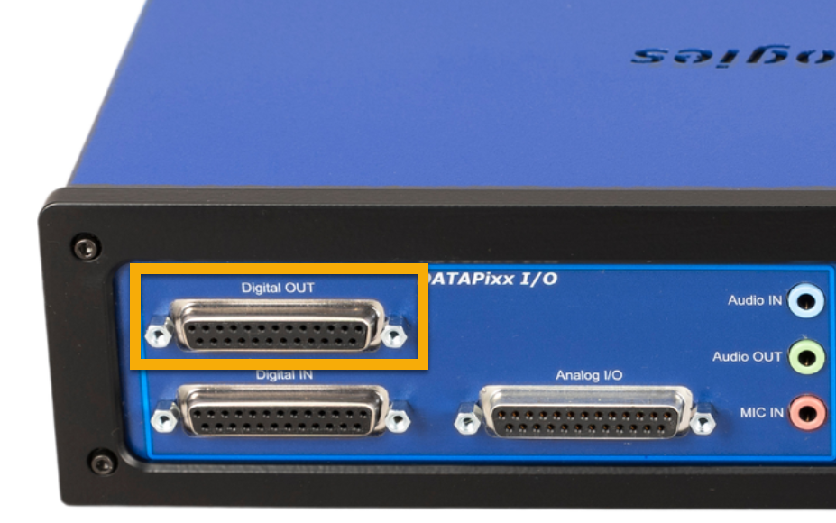
The digital output port on your VPixx hardware supports up to 24 pins or “channels” for TTL signalling. Your receiver will have a set number of channels for inputs, typically between 8-24 channels. By signalling events on multiple channels, we can communicate different unique patterns to indicate unique events in our experiment.

Principles of Pixel Mode

For any given frame of video, the video data passes from your experiment PC’s graphics card to VPixx hardware before being shown on the display. If the hardware is operating in Pixel Mode, the voltages on the digital out port are automatically set based on the colour of the top left-most pixel in that video frame.

The animation below shows an exaggerated top left pixel and the resulting digital output.

PixelModeGifLayers.gif

Each of our digital output channels is associated with a unique bit plane of the R, G or B colour values of the pixel. In other words, in a standard display with 2^24 unique colours available, we can generate 2^24 unique digital signals on our digital output port. That’s over 16 million unique event markers!

Pixel Mode is designed to be program-agnostic. If the mode is enabled on your hardware, you can use any software you like to run your experiment, from PsychoPy to Powerpoint. As long as you can control the colour value of the top left pixel of the experiment display, you can send Pixel Mode digital signals.

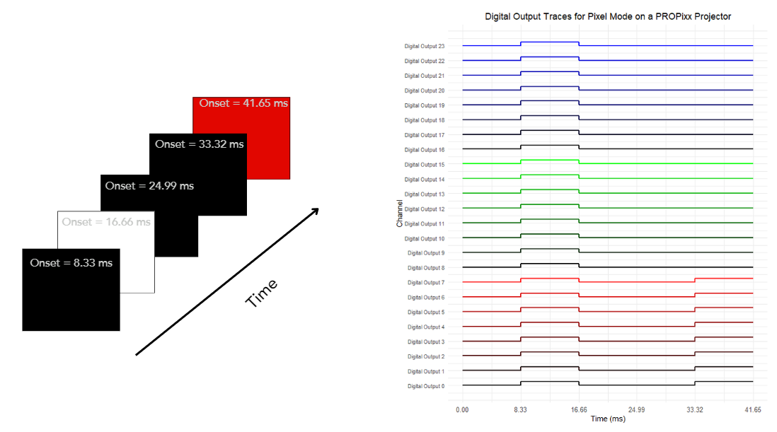
Pixel Mode updates on every video frame. If you maintain the same pixel value across multiple frames, the digital output will also remain the same. The state of each digital output channel will only change when the pixel value does. Here’s an example of what the changing channel values look like, on a PROPixx. Note the transition from black on frame 1 (all channels low) to white on frame 2 (all channels high) to black for two frames, and then full red on frame 5 (first 8 channels high).

image-20240906-194340.png

Pixel Mode behaviour on a PROPixx projector operating at 120 Hz. Note the Pixel Mode signal precedes the video frame by precisely 8.33 ms (1 frame at 120 Hz). See the next section for an explanation.

Pixel Mode timing vs. display behaviour

Pixel Mode values are detected in the video signal before being passed to the display. This causes a short, consistent temporal offset between digital signal onset and physical screen illumination.

This happens because when our Pixel Mode value is detected, the video data for the frame is still in the process of being transmitted. We need additional time to collect enough video data to start physically illuminating the display.

VPixx displays have deterministic, or fully characterized, timing properties. Therefore we can say the exact temporal offset between the timing of the digital signals and physical pixel illumination, for any of our displays. The table below shows a summary of temporal offsets for different displays:

Display

Marker leads physical screen illumination by:

Notes

VIEWPixx /EEG

6 ms @ 120 Hz

VIEWPixx /3D

6 ms @ 120 Hz

Scanning backlight recommended

PROPixx projector

1 full frame (e.g., 8.33 ms @ 120 Hz)

For Pixel Mode with custom PROPixx sequencers, the ‘composite’ image is typically used for Pixel Mode.

DATAPixx and DATAPixx3 with third-party monitor

Variable, depends on the monitor

We recommend a one-time photodiode measurement to determine the marker-illumination offset.

Pixel Mode value calculator

We now know how Pixel Mode works, how communication between devices operates, and what kind of temporal offsets to expect from our event markers. Next, we have to decide how to determine our Pixel Mode values!

The easiest method is to simply use our calculator. Select the digital output channels you want to be ‘high’ on a given frame, and the calculator will tell you what RGB value you need to draw in the top left corner of the display.

It’s important to remember that your receiver may not label the digital input channels in the same manner. You can refer to your cable wiring diagram to see how the digital output channels map to your receiver channels, to help you interpret the incoming signal.

If you prefer to calculate triggers directly in your code, you can use the following formulae:

in MATLAB
MATLAB
% Define what dout channels we want to be high on this frame
doutChannelsHigh = [0, 2, 4];

% Determine the decimal value associated with this unique pattern
desiredTriggerValue = sum(2.^doutChannelsHigh);

% Convert to RGB255 value
% MATLAB uses uint8 for 8-bit values
pixelColor = [mod(desiredTriggerValue, 256), ...
              bitshift(desiredTriggerValue, -8), ...
              bitshift(desiredTriggerValue, -16) ];
in Python
PY
#Define what doutchannels we want to be high on this frame
doutChannelsHigh = [0,2,4]

#Determine the decimal value associated with this unique pattern
desiredTriggerValue = sum(2**i for i in doutChannelsHigh)

#Convert to RGB255 value
pixelColor = [ triggerValue%256, (triggerValue>>8)%256, (triggerValue>>16)%256]
Manual calculation

The state of each channel from DOut 0-23 is represented as a value in a 24-digit binary string. The positions are read from right to left, starting with 0, i.e.,:

b23 b22 b21 b20 …. b0

For the digital output port, “high” states are represented by 1s, while “low” states are 0s. For example:

0100 0000 0000 1000 0000 0001

In this string, b22, b15 and b0 are high. All other bits are low.

In Pixel Mode, bits are grouped into different colour channels, starting with red on the right. To continue our example:
0100 0000 0000 1000 0000 0001

We treat these as three separate 8-bit binary values:
0100 0000
0000 1000
0000 0001

The decimal equivalent D, of each binary number is given by:
D = b7​ x 27+ b6​ x 26 + b5 x 25 + b4​ x 24+ b3 x 23+ b2 x 22+ b1 x 21+ b0 x 20

This is the value we pass to our colour channel. So for example, to calculate our blue colour value:
Dblue = 0​ x 27+ 1​ x 26 + 0 x 25 + 0​ x 24+ 0 x 23+ 0 x 22+ 0 x 21+ 0 x 20 = 64

We repeat this for each colour channel, which gives us a pixel value of:
[1, 8, 64]

Pixel Mode variants

There are three different variants of Pixel Mode, which control all or a subset of the digital output channels available. If channels are “ignored” it means other systems can use those channels, and Pixel Mode signals will not overwrite them. See below for each variant and description:

Mode

Description

Notes

Pixel Mode RGB

All 24 channels of the digital output are controlled by the top left pixel’s RGB colour value

Ideal for situations where receiver does not require other digital input.

Pixel Mode GB

Channels 8-23 of the digital output are controlled by the top left pixel’s green and blue colour value. Channels 0-7 are ignored.

Ideal for situations where first 8 channels are in use, e.g., if button box activity is being forwarded

Pixel Mode B*

Channels 16-23 of the digital output are controlled by the top left pixel’s blue colour value. Channels 0-15 are ignored.

Ideal for situations where first 16 channels are in use, e.g., if RESPONSEPixx /MRI 10-button actitivty is being forwarded

*Pixel Mode B was introduced in release 1.8.1 (September 2024) and is only available for the DATAPixx3 with firmware revision 27 or higher.

Enabling Pixel Mode on VPixx hardware

Below is a list of VPixx hardware that supports Pixel Mode, and how to enable the mode on that particular device:

VIEWPixx /EEG

Pixel Mode RGB is on by default. No action is required.

VIEWPixx and VIEWPixx /3D

Pixel Mode B is currently only available for the DATAPixx3. It cannot be used with a VIEWPixx display.

  • In LabMaestro:

    • Double-click on the VIEWPixx monitor in the Environment section of the Project panel

    • In Digital IO, select the desired Pixel Mode variant from the Output Mode dropdown menu

    • Optional: Save as Power-On settings to remain in this mode after restarting the device

  • In MATLAB:

    • Set the mode using the following commands

      MATLAB
      %Set preferred mode:
      %0 is Pixel Mode RGB
      %1 is Pixel Mode GB
      mode = 0;
      
      Datapixx('Open');
      Datapixx('EnablePixelMode', mode);
      Datapixx('RegWr');
      
      %To disable:
      Datapixx('DisablePixelMode');
      Datapixx('RegWr');
  • In Python

    • Set the desired mode using one of the following commands

      PY
      from pypixxlib import _libdpx as dp
      
      #Connect to hardware
      dp.DPxOpen()
      
      #Ensure pixel mode enabled-- uncomment the desired variant
      #dp.DPxEnableDoutPixelMode()
      #dp.DPxEnableDoutPixelModeGB()
      dp.DPxWriteRegCache()
      
      #To disable:
      #dp.DPxDisableDoutPixelMode()
      #dp.DPxDisableDoutPixelModeGB()
      dp.DPxWriteRegCache()
DATAPixx and DATAPixx3

Pixel Mode B is currently only available for the DATAPixx3. It cannot be used with a DATAPixx.

  • In LabMaestro:

    • Double-click on the DATAPixx device in the Environment section of the Project panel

    • In Digital IO, select the desired Pixel Mode variant from the Output Mode dropdown menu

    • Optional: Save as Power-On settings to remain in this mode after restarting the device

  • In MATLAB:

    • Set the mode using the following commands

      MATLAB
      %Set preferred mode:
      %0 is Pixel Mode RGB
      %1 is Pixel Mode GB
      %2 is Pixel Mode B
      mode = 0;
      
      Datapixx('Open');
      Datapixx('EnablePixelMode', mode);
      Datapixx('RegWr');
      
      %To disable:
      Datapixx('DisablePixelMode');
      Datapixx('RegWr');
  • In Python

    • Set the desired mode using one of the following commands

      PY
      from pypixxlib import _libdpx as dp
      
      #Connect to hardware
      dp.DPxOpen()
      
      #Ensure pixel mode enabled-- uncomment the desired variant
      #dp.DPxEnableDoutPixelMode()
      #dp.DPxEnableDoutPixelModeGB()
      #dp.DPxEnableDoutPixelModeB()
      dp.DPxWriteRegCache()
      
      #To disable:
      #dp.DPxDisableDoutPixelMode()
      #dp.DPxDisableDoutPixelModeGB()
      #dp.DPxDisableDoutPixelModeB()
      dp.DPxWriteRegCache()
PROPixx projector

Pixel Mode B is currently only available for the DATAPixx3. It cannot be used with a PROPixx Controller.

  • In LabMaestro:

    • Double-click on the DATAPixx3 or PROPixx Controller driving the projector. This is found in the Environment section of the Project panel

    • In Digital IO, select the desired Pixel Mode variant from the Output Mode dropdown menu

    • Optional: Save as Power-On settings to remain in this mode after restarting the device

  • In MATLAB:

    • Set the mode using the following commands

      MATLAB
      %Set preferred mode:
      %0 is Pixel Mode RGB
      %1 is Pixel Mode GB
      %2 is Pixel Mode B
      mode = 0;
      
      Datapixx('Open');
      Datapixx('EnablePixelMode', mode);
      Datapixx('RegWr');
      
      %To disable:
      Datapixx('DisablePixelMode');
      Datapixx('RegWr');
  • In Python

    • Set the desired mode using one of the following commands

      PY
      from pypixxlib import _libdpx as dp
      
      #Connect to hardware
      dp.DPxOpen()
      
      #Ensure pixel mode enabled-- uncomment the desired variant
      #dp.DPxEnableDoutPixelMode()
      #dp.DPxEnableDoutPixelModeGB()
      #dp.DPxEnableDoutPixelModeB()
      dp.DPxWriteRegCache()
      
      #To disable:
      #dp.DPxDisableDoutPixelMode()
      #dp.DPxDisableDoutPixelModeGB()
      #dp.DPxDisableDoutPixelModeB()
      dp.DPxWriteRegCache()

Troubleshooting Pixel Mode

Pixel Mode requires something called 1-1 pixel identity passthrough. Put simply, the pixel values you draw in your software must match the pixel values read by the display.

If your pixels become altered in some way, Pixel Mode will pass the wrong triggers to your hardware.

To learn more about Pixel Identity Passthrough and how to verify it on your system, see our troubleshooting guide: What is Pixel Identity Passthrough?

A note about sub-frame timing of pixel illumination

Pixel Mode provides microsecond-precise triggering based on when the video signal reaches our hardware.

On the PROPixx projector, the entire screen illuminates simultaneously. Digital signals are thus in lockstep with every pixel on the display.

Our VIEWPixx monitors use a scanning backlight that moves down the screen throughout a video frame. Thus, the exact timing of pixel illumination on a VIEWPixx is location-specific. Of course, this delay is always less than the screen refresh rate (8.33 ms/frame at 120Hz).

If you want to characterize the exact offset between your trigger (based on the start of the video frame), and the illumination of the specific patch of pixels where your stimulus appears on a VIEWPixx, you will need to perform a one-time measurement using a photodiode placed over that stimulus’ position on the screen. This will give you the precise sub-frame offset between the trigger and the spatially-dependent onset of your stimulus. 

Example: Using Pixel Mode to send an event marker indicating the stimulus onset

In LabMaestro

Ensure Pixel Mode is enabled on your VPixx hardware. See the section above on how to enable it on different VPixx devices.

Future versions of LabMaestro will automate Pixel Mode triggering. For now, simply draw a rectangle region in the top left corner of the display at the beginning of the stimulus epoch, and set the colour according to your desired digital output. Ensure any timing behaviour (e.g., onset delay) matches that of the stimulus region.

In MATLAB
MATLAB
% Open a fullscreen window
screenid = max(Screen('Screens'));
[window, windowRect]=PsychImaging('OpenWindow', screenid, 0);

%Enable Pixel Mode
Datapixx('Open');
Datapixx('EnablePixelMode', 1);
Datapixx('RegWr');

% Pixel Mode pixel properties
pixelPos = [0, 0];
pixelCol = [19,0,0]; %channels 0,1,4 to high

% Define stimulus
textString = 'Hello World';
textColor = [255, 255, 255];

% Draw the text "Hello World" in the middle of the display
DrawFormattedText(window, textString, 'center', 'center', textColor);

% Draw the single pixel in the top-left corner
Screen('DrawDots', window, pixelPos, 1, pixelCol, [], 1);

% Flip to the screen
Screen('Flip', window);

% Wait for a spacebar press to exit
KbName('UnifyKeyNames');
exitKey = KbName('space');

while true
    % Check the keyboard for a key press
    [keyIsDown, ~, keyCode] = KbCheck;
    
    % Exit on spacebar press
    if keyIsDown && keyCode(exitKey)
        break;
    end
end

% Close the Psychtoolbox window
sca;

%Shut down
Datapixx('DisablePixelMode');
Datapixx('RegWr');
Datapixx('Close');
In PsychoPy Builder

Ensure Pixel Mode is enabled on your VPixx hardware. See the section above on how to enable it on different VPixx devices.

In Builder, create a polygon stimulus (a line or a rectangle) in the top left corner of the full-screen display. Ensure this stimulus has a width and height of at least 1 pixel. PsychoPy Builder uses a normalized colour space (e.g., colour values from 0-1). To convert RGB255 to this space and determine the normalized colour value for your desired Pixel Mode output, simply divide each channel value obtained in our calculator by 255.

Note that PsychoPy Builder may use interpolation and gamma correction on some stimuli by default. This can usually be turned off by editing the experiment code directly (e.g., setting the Pixel Mode ImageStim property interpolate=False).

The timing properties of the stimulus should match those of your experiment stimulus, in terms of onset delay.

JavaScript errors detected

Please note, these errors can depend on your browser setup.

If this problem persists, please contact our support.