Cathode ray tube (CRT) screens are recognizable by their heavy, boxy shape. They are largely considered outdated, and have been replaced by high resolution liquid crystal displays (LCDs). In fact, it is increasingly difficult to find a modern graphics card that supports the analog video protocol required to drive a CRT display. Simply put, the world of displays has gone digital.
So, why are vision scientists concerned about recreating a CRT monitor?

The answer has to a lot to do with the limitations of early generation LCDs, and the consequences these limitations have for presentation of highly-controlled visual stimuli.
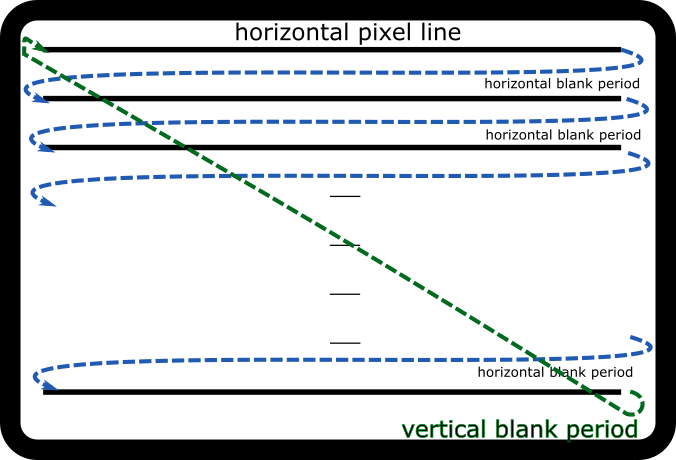
CRT monitors are comprised of a layer of phosphors, organic material which glows briefly when struck by an electron beam from a gun inside the monitor. The beam rapidly scans down the display, from left to right, top to bottom, in a pattern known as a raster. At the end of each row, the beam briefly stops and skips back to the start of the next row; this is known as a horizontal blanking period. When the gun reaches the bottom of the screen, there is a longer, vertical blanking period while the gun jumps back to the top of the display to start the next frame.
In an analog video signal, the cue for the gun to jump back to the top of the display is called a vertical sync pulse. This pulse, which is also included in digital video communication protocols, effectively marks the beginning of the next frame of the video signal. We will return to the vsync signal in the next section, where we talk about video synchronization.
Commercial LCD panels do not illuminate in a raster pattern. Instead, they have a grid of pixels which are all simultaneously illuminated by a backlight. The light shines through a filter that blocks all light that is not horizontally polarized. The light then passes through a liquid crystal layer, where molecules rotate the polarization of the light between 0-90 degrees. The degree to which a given molecule rotates the light depends on its structure. When a charge is passed through the molecules, their structure changes and the light can pass through with more or less polarization.
After the light passes through the LCD layer, a red-green-blue filter limits the output spectrum to a specific colour of light. A second filter allows only vertically polarized light to pass to the display, meaning any light that was not altered by the liquid crystal layer (e.g., still horizontally polarized) does not pass through, and the pixel will be fully dark.

Every time we change the value of an individual pixel on the display, we must change the structure of the molecules responsible for that pixel’s RGB intensity. Depending on the display, it can take several milliseconds for the molecules in the panel to fully stabilize in a new position. The time it takes for a single pixel to stabilize is referred to as the pixel response time.
Typically, an LCD backlight is on continuously, meaning the display shows the entire change in pixel luminance while the molecules change configuration. This ramp can last around 5 milliseconds on a typical LCD transitioning from black to white, and is visible in photodiode recordings like the one shown below.
A very slow pixel response means that pixel transitions trail behind the speed of the video signal. This leads to images bleeding across several frames, an artifact known as ghosting.
Another consequence of a slow pixel response time is motion blur. Especially for high contrast, fast-moving objects, pixel stabilization lags behind the movement speed. As a result, the edges of the moving object are smeared.
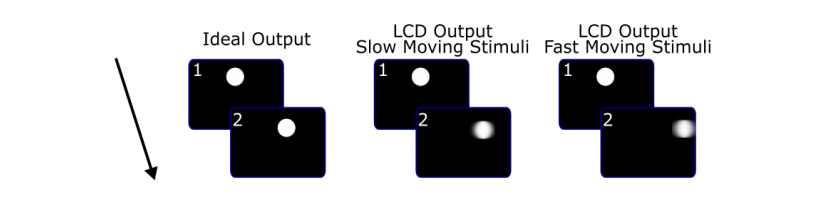
These display artifacts are not ideal for vision scientists looking for tightly controlled stimuli, particularly high contrast, moving stimuli.
CRT scanning patterns don’t produce the same kind of ghosting and blurring artifacts, which is why historically, CRTs have been the monitor of choice for vision science. However, CRT displays have their own limitations, notably their size, lack of availability and graphics support, and limited refresh rates (typically less than 75 Hz).
In response to the need for a modern display with crisp CRT-like features, VPixx has developed a high resolution, 120 Hz LCD display with a scanning backlight that mimics the raster pattern of a CRT monitor.

With a scanning backlight, individual pixels are not illuminated until the molecules in the liquid crystal layer are almost fully stabilized. The perceptual result is cleaner frame transitions, with minimal ghosting and reduced motion blur.
Consider the pixel transition on a VIEWPixx /3D, as measured by a photodiode. The image on the left below shows the pixel’s illumination as it transitions from black to white to black, without the scanning backlight enabled. The rise time to peak illumination is 5 ms, with a fall time of 1 ms. The image on the right shows the illumination of a pixel with the backlight enabled (black-white-black-white-black). Here, rise and fall time are both 1 ms.
black → white → black
black → white → black repeating
The VIEWPixx /EEG has the scanning backlight feature enabled by default. On the VIEWPixx /3D this feature can be enabled and disabled via software tools.