Forwarding RESPONSEPixx Button Activity to a Third-Party Receiver
This guide demonstrates how to enable automated forwarding of RESPONSEPixx button activity to a third-party receiver (e.g., an OPM, MEG or EEG recording device).
This guide covers:
Basic RESPONSEPixx cabling
Additional cabling recommendations to connect to third-party receivers
Software tools to enable automated forwarding
Examples in Python and MATLAB
Basic RESPONSEPixx cabling
Electrical RESPONSEPixx units are connected directly to the Digital Input port on the DATAPixx3.
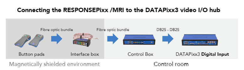
Fibre optic RESPONSEPixx units have a few more components. Below is a simplified graphic of a RESPONSEPixx /MRI installation, using our 10-button RESPONSEPixx /MRI.
Connecting a RESPONSEPixx /MRI to the DATAPixx3 Digital Input
The DATAPixx3 is connected to the experiment PC via a USB connection. With this configuration, you can register button activity directly in your experiment software. We have many demos showcasing how to read and interpret button box activity using our software tools:
The best way to send button press activity to a third-party receiver is via automated signal forwarding. This is done through our DATAPixx3 or one of our other I/O hubs like the PROPixx Controller.
To forward button activity to the receiver, the DATAPixx3 hardware is configured to listen for button presses, and automatically send a digital output waveform whenever button activity is detected.
This approach has several key advantages:
Flexible access to participant responses. Both your experiment PC and receiver retain a copy of the button activity. This means you have multiple methods to access your participant responses during and after your experiment.
Combine button activity with other triggers from the DATAPixx3. Routing signals through the DATAPixx3 allows you to add custom output triggers unrelated to your participant input. For example, you may wish to send additional digital triggers to indicate visual stimulus onsets, either manually or via .
Condense button activity to fewer channels. Some receivers only have a limited number of inputs, typically a multiple of 8. Depending on your lab, you may have more buttons than input channels, or you may have channels that are in use by other equipment. The DATAPixx3 can be configured to send unique signals representing each type of button on a single digital output channel (e.g., one pulse for a red button, two pulses for blue), thus freeing up other channels as needed.
Best possible timing. Some third-party receivers have a slow sampling rate. By retaining a copy of button activity on our hardware, you ensure that you have precise timing of participant responses regardless of the receiver sampling rate.
Connecting your third-party hardware
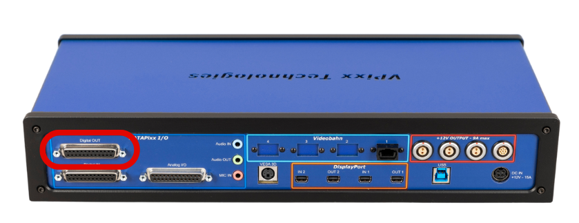
The DATAPixx3 passes digital triggers to third-party receivers via the DB25 Digital Output port on the back of the unit:
DATAPixx3 unit (rear) with the Digital Output port indicated
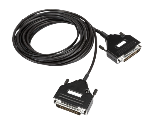
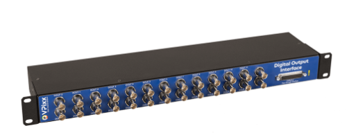
There are two general methods to connect your third-party receiver’s digital input receiver to this output: either via a custom cable, or a breakout box. You can learn more about these options on our cabling solutions product page.
Custom DB25-DB25 trigger cable
Digital output breakout box
VPixx offers several standard cables designed in partnership with EEG and MEG manufacturers. We also make fully custom cables for our customers as needed.
For simple systems, a single custom cable is typically sufficient. For more complex layouts, particularly with multiple inputs and outputs, you may want to use a breakout box for added flexibility.
If you have any doubts about how to connect our equipment to your receiver, feel free to reach out to our staff scientists, who are happy to provide guidance. Please make sure to let us know the make and model of your receiver and your desired cable length, and include any documentation you might have related to the third-party hardware’s port and pin mappings.
Enabling button activity forwarding on your DATAPixx3
Once you have connected the following:
RESPONSEPixx → DATAPixx3 digital input
DATAPixx3 → PC
DATAPixx3 digital output → third-party receiver
It’s time to configure your DATAPixx3 for button activity forwarding.
To do this, you will first need to ensure your PC has a copy of our software tools installed. You will also need access to either Python or MATLAB scripting; we provide code examples for both options below.
Whichever software tool you prefer, make sure you install our API tools for that software before running the code. You can find more details about our MATLAB API installation here, and our Python API installation (including adding it to PsychyoPy) here.
Button activity forwarding uses a special schedule that pre-loads one or more digital waveforms onto the DATAPixx3’s onboard memory. Button activity triggers the playback of waveforms on the digital output, which is read by your receiver. This forwarding is near-instantaneous; you may however see a delay if your receiver has a particularly slow sampling rate.
Output waveforms are customizable. You can configure them to:
play on any digital output channel
play at different speeds/durations
play custom pulse sequences
trigger on a button press, release or both
The custom waveform’s address in DATAPixx3 memory determines what button/button activity triggers it. Once the forwarding configuration is saved on your DATAPixx3, it will persist until it is overwritten or the forwarding mode is disabled via a software command.
After writing your waveforms to the DOUT buffer, you need to define the DOUT playback schedule using ‘SetDoutSchedule.’
The maximum size of the waveform in memory defined in the schedule is the number of samples in the waveform + 1. The reason for this is that when the schedule starts, the number of samples actually “played” will be the number of samples specified in ‘SetDoutSchedule’ - 1.
Example 1: Simple button press forwarding with the RESPONSEPixx /MRI 10-button
Our first example shows the simplest case of button activity forwarding using the RESPONSEPixx /MRI 10-button unit.
Pressing any button triggers a 50 ms pulse on a unique digital output channel. The output channel value is the same as the input channel value, effectively making this a 1-1 mapping.
MATLAB Example
MATLAB
function enableDinDoutPassthrough()
%This function enables a 1-1 DIN to DOUT passthrough on the DATAPixx3
%We use the RESPONSEPixx MRI 10-button as an example.
%This script only needs to be run once; it will persist on the device until a
%disable command is passed.

% Open Datapixx, stop any schedules which might already be running, and clear any
%existing forwarding behaviour
Datapixx('Open');
Datapixx('StopAllSchedules');
Datapixx('DisableDoutButtonSchedules');
Datapixx('RegWrRd');

%Step 1 - Generate automated DOUT waveforms and load them into DATAPixx3
%memory. For reference, DIN bit assignment for RESPONSEPixx /MRI 10-button is:
%Red Left = 0
%Yellow Left = 1
%Green Left = 2
%Blue Left = 3
%White Left = 4
%Red Right = 5
%Yellow Right = 6
%Green Right = 7
%Blue Right = 8
%White Right = 9

%Pressing a button will trigger a 50 ms pulse on the corresponding DOUT channel.
%The playback speed is determined by samplesPerSecond and triggerLength.
%Adjust either to change trigger lengths. Note some receivers cannot detect very
%short pulses.

triggerLength = 50; %ms
samplesPerSecond = 1000; %s
waveformOnset = 0; %s
maxSamples = triggerLength+1; %maximum size of waveform in memory
doutBufferBaseAddr = 0; %Starting hardware address for button waveforms
doutButtonSchedulesMode  = 1; %Waveforms start on a rising edge only, MRI units

%Define bits for each button (0-9)
bits = linspace(0,9,10);

%Simple loop to write waveforms into hardware.
%Buffer address for each DIN channel for a rising edge behaviour is baseAddress + 4069*DIN
for k = 1:numel(bits)
    waveform = repmat(2^bits(k), 1, triggerLength);
    bufferAddress = doutBufferBaseAddr + 4096*bits(k);
    Datapixx('WriteDoutBuffer', waveform, bufferAddress);
end

%Step 2 - Pass playback settings to device and enable passthrough mode
Datapixx('SetDoutSchedule', waveformOnset, samplesPerSecond, maxSamples, doutBufferBaseAddr);

%Filter out button bounces (mostly a concern for electrical units, doesn't hurt)
Datapixx('EnableDinDebounce');

Datapixx('EnableDoutButtonSchedules', doutButtonSchedulesMode); %see DisableDoutButtonSchedules to turn off this mode

%Push commands to hardware and sever connection
Datapixx('RegWrRd');
Datapixx('Close');

fprintf('\n\nAutomatic buttons schedules running\n\n');

end
Python example
Python
import numpy as np
from pypixxlib import _libdpx as dp

def enable_din_dout_passthrough():
    #This function enables a 1-1 DIN to DOUT passthrough on the DATAPixx3
    #We use the RESPONSEPixx MRI 10-button as an example.
    #This script only needs to be run once; it will persist on the device until a
    #disable command is passed.

    # Open Datapixx and clear any forwarding behaviours
    dp.DPxOpen()
    dp.DPxDisableDoutButtonSchedules()
    dp.DPxUpdateRegCache()

    # Step 1 - %Step 1 - Generate automated DOUT waveforms and load them into DATAPixx3
    #memory. For reference, DIN bit assignment for RESPONSEPixx /MRI 10-button is:
    #Red Left = 0
    #Yellow Left = 1
    #Green Left = 2
    #Blue Left = 3
    #White Left = 4
    #Red Right = 5
    #Yellow Right = 6
    #Green Right = 7
    #Blue Right = 8
    #White Right = 9

    #Pressing a button will trigger a 50 ms pulse on the corresponding DOUT channel.
    #The playback speed is determined by samplesPerSecond and triggerLength.
    #Adjust either to change trigger lengths. Note some receivers cannot detect very
    #short pulses.

    trigger_length = 50  # ms
    samples_per_second = 1000  # Hz
    dout_buffer_base_addr = 0  # Initial address for button waveforms
    dout_button_schedules_mode = 1  # Triggers start on a rising edge; 1 for MRI

    #Define bits for each button (0-9)
    bits = np.arange(10)

    #Simple loop to write waveforms into hardware.
    #Buffer address for each DIN channel for a rising edge behaviour is baseAddress + 4069*DIN
    for bit in bits:
        waveform = list(np.full(trigger_length, 2 ** bit, dtype=np.uint32))
        buffer_address = dout_buffer_base_addr + 4096 * bit
        dp.DPxWriteRam(buffer_address, waveform)

    # %Step 2 - Pass playback settings to device and enable passthrough mode
    #configure buffer-- only need to configure the first one, rest will follow the same format
    dp.DPxSetDoutBuff(dout_buffer_base_addr + 4096 * 0, trigger_length*2)
    dp.DPxSetDoutSched(0, samples_per_second, 'hz', trigger_length+1)

    #Filter out button bounces (mostly a concern for electrical units, doesn't hurt)
    dp.DPxEnableDinDebounce()
    dp.DPxEnableDoutButtonSchedules()
    dp.DPxSetDoutButtonSchedulesMode(dout_button_schedules_mode)

    %Push commands to hardware and sever connection
    dp.DPxUpdateRegCache()
    dp.DPxClose()

    print('\n\nAutomatic button schedules running\n\n')

# Call the function
enable_din_dout_passthrough()
Example 2: Forwarding RESPONSEPixx handheld button activity on a single channel
Our second example shows a more complex case of button forwarding, in which triggers/pulses encoding button events are sent on a single Digital Output channel. We differentiate between the different button presses by sending a pulse train, composed of 100ms-duration pulses, with the number of pulses corresponding to the button’s Digital Input channel value +1. Once again, we use the RESPONSEPixx /MRI 10-button unit.
MATLAB Example
MATLAB
function forwardButtonActivityAsPulseTrains()
%This function enables button press activity on DIN to send a corresponding pulse train on DOUT 0, on the DATAPixx3
%We use the RESPONSEPixx MRI 10-button as an example.
%This script only needs to be run once; it will persist on the device until a
%disable command is passed.

% Open Datapixx, stop any schedules which might already be running, and clear any
%existing forwarding behaviour
Datapixx('Open');
Datapixx('StopAllSchedules');
Datapixx('DisableDoutButtonSchedules');
Datapixx('RegWrRd');

%Step 1 - Generate automated DOUT waveforms and load them into DATAPixx3
%memory. For reference, DIN bit assignment for RESPONSEPixx /MRI 10-button is:
%Red Left = 0
%Yellow Left = 1
%Green Left = 2
%Blue Left = 3
%White Left = 4
%Red Right = 5
%Yellow Right = 6
%Green Right = 7
%Blue Right = 8
%White Right = 9

%Pressing a button will trigger a train of 100ms-duration pulses on a single DOUT channel (DOUT0), the number of pulses will correspond to the button's DIN channel + 1.
%The playback speed is determined by samplesPerSecond and triggerLength.
%Adjust either to change trigger lengths. Note some receivers cannot detect very
%short pulses.

triggerLength = 100; %ms
samplesPerSecond = 1000; %s
waveformOnset = 0; %s
maxSamples = (triggerLength*2*10); %maximum size of waveform in memory; should be less than 4096, which is the maximum size allowed for each button schedule
doutBufferBaseAddr = 0; %Starting hardware address for button waveforms
doutButtonSchedulesMode  = 0; %Waveforms start on a rising edge only, MRI units

%Define bits for each button (0-9)
bits = linspace(0,9,10);

%Simple loop to write waveforms into hardware.
%Buffer address for each DIN channel for a rising edge behaviour is baseAddress + 4069*DIN
for k = 1:numel(bits)
    waveform = [repmat(1, 1, triggerLength),repmat(0,1,triggerLength)];
    full_waveform = repmat(waveform,1,k); % repeat the pulse a requisite number of times
    full_waveform(end+1:end+(maxSamples - length(full_waveform))) = 0; %pad the rest of the values with zero
    bufferAddress = doutBufferBaseAddr + 4096*bits(k);
    Datapixx('WriteDoutBuffer', full_waveform, bufferAddress);
end

%Step 2 - Pass playback settings to device and enable passthrough mode
Datapixx('SetDoutSchedule', waveformOnset, samplesPerSecond, maxSamples+1, doutBufferBaseAddr);

%Filter out button bounces (mostly a concern for electrical units, doesn't hurt)
Datapixx('EnableDinDebounce');

Datapixx('EnableDoutButtonSchedules', doutButtonSchedulesMode); %see DisableDoutButtonSchedules to turn off this mode

%Push commands to hardware and sever connection
Datapixx('RegWrRd');
Datapixx('Close');

fprintf('\n\nAutomatic buttons schedules running\n\n');
end
Python example
Python
import numpy as np
from pypixxlib import _libdpx as dp

def forwardButtonActivityAsPulseTrains():
    # This function enables button press activity on DIN to send a corresponding pulse train on DOUT 0, on the DATAPixx3
    #The number of pulses will correspond to the DIN bit of the pressed button +1, e.g. A press on Red button/DIN 0 will result in 1 pulse on DOUT0
    # We use the RESPONSEPixx MRI 10-button as an example.
    # This script only needs to be run once; it will persist on the device until a
    # disable command is passed.

    # Open Datapixx and clear any forwarding behaviours
    dp.DPxOpen()
    dp.DPxDisableDoutButtonSchedules()
    dp.DPxUpdateRegCache()

    # Step 1 - %Step 1 - Generate automated DOUT waveforms and load them into DATAPixx3
    # memory. For reference, DIN bit assignment for RESPONSEPixx /MRI 10-button is:
    # Red Left = 0
    # Yellow Left = 1
    # Green Left = 2
    # Blue Left = 3
    # White Left = 4
    # Red Right = 5
    # Yellow Right = 6
    # Green Right = 7
    # Blue Right = 8
    # White Right = 9

    # Pressing a button will trigger a train of 100ms-duration pulses on a single DOUT channel (DOUT0), the number of pulses will correspond to the button's DIN channel + 1.
    # The playback speed is determined by samplesPerSecond and triggerLength.
    # Adjust either to change trigger lengths. Note some receivers cannot detect very
    # short pulses.

    trigger_length = 100  # ms
    samples_per_second = 1000  # Hz
    maxSamples = (trigger_length * 2 * 10); # maximum size of waveform in memory; should be less than 4096, which is the maximum size allowed for each button schedule
    dout_buffer_base_addr = 0  # Initial address for button waveforms
    dout_button_schedules_mode = 1  # Triggers start on a rising edge; 1 for MRI

    # Define bits for each button (0-9)
    bits = np.arange(10)

    # Simple loop to write waveforms into hardware.
    # Buffer address for each DIN channel for a rising edge behaviour is baseAddress + 4069*DIN
    for bit in bits:
        waveformHigh = list(np.full(trigger_length, 1, dtype=np.uint32)) #create high part of pulse
        waveformLow = list(np.full(trigger_length, 0, dtype=np.uint32)) #create low part of pulse
        waveform = (waveformHigh + waveformLow)*(bit+1) #repeat the pulse for the bit value corresponding to button +1
        waveform_zeros = list(np.full(maxSamples-len(waveform), 0, dtype=np.uint32))  #pad the rest of samples with 0s
        waveform = waveform + waveform_zeros #pad the rest of samples with 0s
        buffer_address = dout_buffer_base_addr + 4096 * bit
        dp.DPxWriteRam(buffer_address, waveform)

    # %Step 2 - Pass playback settings to device and enable passthrough mode
    # configure buffer-- only need to configure the first one, rest will follow the same format

    dp.DPxSetDoutSchedule(0.0,samples_per_second,maxSamples+1,dout_buffer_base_addr)

    # Filter out button bounces (mostly a concern for electrical units, doesn't hurt)
    dp.DPxEnableDinDebounce()
    dp.DPxEnableDoutButtonSchedules()
    dp.DPxSetDoutButtonSchedulesMode(dout_button_schedules_mode) #Push commnds to hardware and sever connection
    dp.DPxUpdateRegCache()
    dp.DPxClose()

    print('\n\nAutomatic button schedules running\n\n')

# Call the function
forwardButtonActivityAsPulseTrains()
Example 3: Combining RESPONSEPixx /MRI button activity and Pixel Mode triggers
Our final example shows how to combine automatic button forwarding with Pixel Mode triggers. As in the first example, we use the RESPONSEPixx /MRI 10-button unit; and pressing any button triggers a 50 ms pulse on a unique digital output channel. The output channel value is the same as the input channel value, effectively making this a 1-1 mapping. Simultaneously, we use Pixel Mode B to send automated triggers on the last 8 digital output channels (DOUT 16-23), based on the Blue channel value in the top-left pixel of the current video frame; we alternate between displaying full-white and full-black frames to set the last 8 digital output channels to all high and all low, respectively.
This demo requires Pixel Mode B, which is only available on the DATAPixx3 with firmware revision 27 or higher. To update your device firmware, see Performing Firmware Updates
MATLAB Example
MATLAB
function enableDinDoutPassthroughAndPixelModeB()
%This function enables a 1-1 DIN to DOUT passthrough on the DATAPixx3, as
%well as  Pixel Mode B to send automated triggers on the last 8 DOUT channels, DOUT 16-23
%We use the RESPONSEPixx MRI 10-button as an example.
%This script only needs to be run once; it will persist on the device until a
%disable command is passed.

% Open Datapixx, stop any schedules which might already be running, and clear any
%existing forwarding behaviour
Datapixx('Open');
Datapixx('StopAllSchedules');
Datapixx('DisableDoutButtonSchedules');
Datapixx('RegWrRd');

%Step 1 - Generate automated DOUT waveforms and load them into DATAPixx3
%memory. For reference, DIN bit assignment for RESPONSEPixx /MRI 10-button is:
%Red Left = 0
%Yellow Left = 1
%Green Left = 2
%Blue Left = 3
%White Left = 4
%Red Right = 5
%Yellow Right = 6
%Green Right = 7
%Blue Right = 8
%White Right = 9

%Pressing a button will trigger a 50 ms pulse on the corresponding DOUT channel.
%The playback speed is determined by samplesPerSecond and triggerLength.
%Adjust either to change trigger lengths. Note some receivers cannot detect very
%short pulses.

triggerLength = 50; %ms
samplesPerSecond = 1000; %s
waveformOnset = 0; %s
maxSamples = triggerLength+1; %maximum size of waveform in memory
doutBufferBaseAddr = 0; %Starting hardware address for button waveforms
doutButtonSchedulesMode  = 1; %Waveforms start on a rising edge only, MRI units

%Define bits for each button (0-9)
bits = linspace(0,9,10);

%Simple loop to write waveforms into hardware.
%Buffer address for each DIN channel for a rising edge behaviour is baseAddress + 4069*DIN
for k = 1:numel(bits)
    waveform = repmat(2^bits(k), 1, triggerLength);
    bufferAddress = doutBufferBaseAddr + 4096*bits(k);
    Datapixx('WriteDoutBuffer', waveform, bufferAddress);
end

%Step 2 - Pass playback settings to device and enable passthrough mode
Datapixx('SetDoutSchedule', waveformOnset, samplesPerSecond, maxSamples, doutBufferBaseAddr);

%Filter out button bounces (mostly a concern for electrical units, doesn't hurt)
Datapixx('EnableDinDebounce');

Datapixx('EnableDoutButtonSchedules', doutButtonSchedulesMode); %see DisableDoutButtonSchedules to turn off this mode

%Push commands to hardware and sever connection
Datapixx('RegWrRd');

fprintf('\n\nAutomatic buttons schedules running\n\n');

%Step 3: Enable Pixel Mode B to send automated triggers on DOUT 16-23 by changing the blue channel value of top-left pixel; we will alternate between showing white and black frames, resulting in DOUT 16-23 channels to alternate between high and low.

%Enable Pixel Mode
Datapixx('EnablePixelMode', 2); %eEnable pixel mode B to automatically send triggers on DOUT 16-23 based on the Blue channel value in the top-left pixel
Datapixx('RegWr');

Screen('Preference', 'SkipSyncTests', 1);
% Open a fullscreen window
screenid = max(Screen('Screens'));
[window, windowRect]=PsychImaging('OpenWindow', screenid, 0);

% Wait for a spacebar press to exit
KbName('UnifyKeyNames');
exitKey = KbName('space');

while true

Screen('FillRect',window,[255 255 255])  %draw white frame; top-left pixel will be 255 on blue channel, corresponding to Pixel Mode B trigger: high on last 8 DOUT channels
Screen('Flip',window);

Screen('FillRect',window,[0 0 0]) %draw blackframe; top-left pixel will be 0 on blue channel, corresponding to Pixel Mode B trigger: low on last 8 DOUT channels
Screen('Flip',window);

[keyIsDown, ~, keyCode] = KbCheck;
if keyIsDown && keyCode(exitKey)
        break;
end

end

% Close the Psychtoolbox window
sca;

%Shut down
Datapixx('DisablePixelMode');
Datapixx('RegWr');
Datapixx('Close');
end
Python example
Python
import keyboard
import numpy as np
from pypixxlib import _libdpx as dp
from psychopy import core, visual


def enable_din_dout_passthrough_pixel_mode():
    # This function enables a 1-1 DIN to DOUT passthrough on the DATAPixx3, as well as  Pixel Mode B to send automated triggers on the last 8 DOUT channels, DOUT 16-23
    # We use the RESPONSEPixx MRI 10-button as an example.
    # This script only needs to be run once; it will persist on the device until a
    # disable command is passed.

    # Open Datapixx and clear any forwarding behaviours
    dp.DPxOpen()
    dp.DPxDisableDoutButtonSchedules()
    dp.DPxUpdateRegCache()

    # Step 1 - %Step 1 - Generate automated DOUT waveforms and load them into DATAPixx3
    # memory. For reference, DIN bit assignment for RESPONSEPixx /MRI 10-button is:
    # Red Left = 0
    # Yellow Left = 1
    # Green Left = 2
    # Blue Left = 3
    # White Left = 4
    # Red Right = 5
    # Yellow Right = 6
    # Green Right = 7
    # Blue Right = 8
    # White Right = 9

    # Pressing a button will trigger a 50 ms pulse on the corresponding DOUT channel.
    # The playback speed is determined by samplesPerSecond and triggerLength.
    # Adjust either to change trigger lengths. Note some receivers cannot detect very
    # short pulses.

    trigger_length = 50  # ms
    samples_per_second = 1000  # Hz
    dout_buffer_base_addr = 0  # Initial address for button waveforms
    dout_button_schedules_mode = 1  # Triggers start on a rising edge; 1 for MRI

    # Define bits for each button (0-9)
    bits = np.arange(10)

    # Simple loop to write waveforms into hardware.
    # Buffer address for each DIN channel for a rising edge behaviour is baseAddress + 4069*DIN
    for bit in bits:
        waveform = list(np.full(trigger_length, 2 ** bit, dtype=np.uint32))
        buffer_address = dout_buffer_base_addr + 4096 * bit
        dp.DPxWriteRam(buffer_address, waveform)

    # %Step 2 - Pass playback settings to device and enable passthrough mode
    # configure buffer-- only need to configure the first one, rest will follow the same format
    dp.DPxSetDoutBuff(dout_buffer_base_addr + 4096 * 0, trigger_length * 2)
    dp.DPxSetDoutSched(0, samples_per_second, 'hz', trigger_length + 1)

    # Filter out button bounces (mostly a concern for electrical units, doesn't hurt)
    dp.DPxEnableDinDebounce()
    dp.DPxEnableDoutButtonSchedules()
    dp.DPxSetDoutButtonSchedulesMode(dout_button_schedules_mode)

    # Push command to hardware
    dp.DPxUpdateRegCache()

    print('\n\nAutomatic button schedules running\n\n')

    #Step 3: Enable Pixel Mode B to send automated triggers on DOUT 16-23 by changing the blue channel value of top-left pixel; we will alternate between showing white and black frames, resulting in DOUT 16-23 channels to alternate between high and low.

    dp.DPxEnableDoutPixelModeB() #enable Pixel Mode B
    dp.DPxUpdateRegCache()

    win = visual.Window(
        screen=1,
        monitor=None,
        fullscr=True,
        pos=[0, 0],
        color='black',
        units="pix"
    )

    # Get the actual size of the full-screen window
    window_width, window_height = win.size

    full_screen_white = visual.Rect(
        win=win,
        width=window_width,
        height=window_height,
        fillColor='white',  # Example fill color
        pos=(0, 0)  # Center the rectangle
    )

    full_screen_black = visual.Rect(
        win=win,
        width=window_width,
        height=window_height,
        fillColor='black',  # Example fill color
        pos=(0, 0)  # Center the rectangle
    )
    while True:
        if keyboard.is_pressed('q'):
            print(" 'q' pressed. Exiting loop.")
            break
        full_screen_white.draw() #draw white frame; top-left pixel will be 255 on blue channel, corresponding to Pixel Mode B trigger: high on last 8 DOUT channels
        win.flip()
        full_screen_black.draw() #draw black frame; top-left pixel will be 0 on blue channel, corresponding to Pixel Mode B trigger: low on last 8 DOUT channels
        win.flip()

    dp.DPxEnableDoutPixelModeB() #disable Pixel Mode B
    dp.DPxUpdateRegCache()
    win.close()
    core.quit()

# Call the function
enable_din_dout_passthrough_pixel_mode()
Enabling button activity forwarding (Digital Passthrough Mode) on your VIEWPixx3 /OLED
Forwarding button activity is also possible on our VIEWPixx3/OLED monitor. By default, the digital output channels of the VIEWPixx3 /OLED are configured to automatically send triggers; however, special Digital Passthrough Modes on the VIEWPixx3/OLED will allow you to automatically forward button activity from a subset of digital output channels, while the remaining digital output channels continue to operate in Pixel Mode. Digital Passthrough essentially “copies” the states of digital inputs, corresponding to RESPONSEPixx buttons, on to a set of digital outputs; there are two different Digital Passthrough Modes:
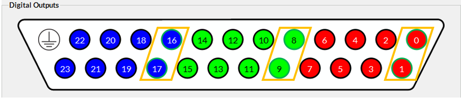
Digital Passthrough for a 5 button RESPONSEPixx: This mode sets the two least-significant bits on the digital output channels driven by the RED channel, GREEN channel, and BLUE channel, in Digital Passthrough mode; these 6 digital outputs correspond to DOUT channel numbers 0, 1, 8, 9, 16 and 17.
The digital output channels that are automatically driven by digital inputs in Digital Passthrough Mode (for a 5 button RESPONSEPixx), outlined in orange
RESPONSEPixx Button
Digital input Channel Number
Digital output driven in Passthrough Mode
Red
0
0
Yellow
1
1
Green
2
8
Blue
3
9
White
4
16
None
5
17
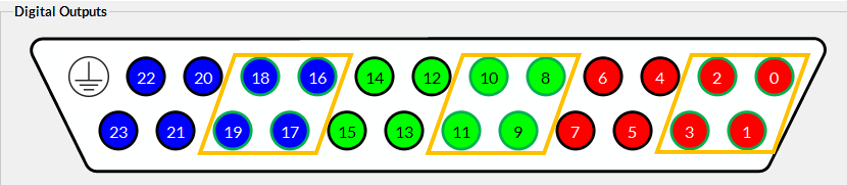
Digital Passthrough for a 10 button RESPONSEPixx: This mode sets the four least-significant bits on the digital output channels driven by the RED channel, GREEN channel, and BLUE channel, in Digital Passthrough mode; these 12 digital outputs correspond to DOUT channel numbers 0, 1, 2, 3, 8, 9, 10, 11, 16, 17, 18 and 19.
The digital output channels that are automatically driven by digital inputs in Digital Passthrough Mode (for a 10 button RESPONSEPixx), outlined in orange
RESPONSEPixx Button
Digital Input Channel Number
Digital Output driven in Passthrough Mode
Red (left)
0
0
Yellow (left)
1
1
Green (left)
2
8
Blue (left)
3
9
White (left)
4
16
Red (right)
5
17
Yellow (right)
6
2
Green (right)
7
3
Blue (right)
8
10
White (right)
9
11
None
10
18
None
11
19
Note, there are alternate versions for each the two Digital Passthrough Modes, detailed above, with the polarity inverted. That is, in the modes above, a button press (on a standard RESPONSEPixx) brings a digital input channel, and its corresponding digital output channel, from high to low, and a button release brings the channels back to high; however, inverting the polarity of the Digital Passthrough Mode, reverses the behavior of the digital output channel: a button press brings the digital output channel from low to high, and a button release brings the channel back to low. See the instructions and examples below for how to enable all the different Digital Passthrough Modes.
Instructions for Enabling Digital Passthrough Mode
Once you have connected the following:
RESPONSEPixx → VIEWPixx3/OLED digital input
VIEWPixx3/OLED → PC
VIEWPixx3/OLED digital output → third-party receiver
It’s time to configure your VIEWPixx3/OLED for button activity forwarding.
To do this, you will first need to ensure your PC has a copy of our software tools installed. Button activity forwarding is implemented through a feature called Digital Passthrough Mode, which can be enabled in our MATLAB API (1.11.3 and up) or Python API (1.11.4 and up), as well as in LabMaestro (1.11.3 and up).
Whichever software tool you prefer, make sure you install our API tools for that software before running the code. You can find more details about our MATLAB API installation here, and our Python API installation (including adding it to PsychyoPy) here.
Below are snippets of code for enabling Digital Passthrough Mode in Matlab and Python.
MATLAB Example
MATLAB
% Open Datapixx
Datapixx('Open');
Datapixx('RegWrRd');

% Enable Digital Passthrough Mode; input arguments corresponding to the different passthrough modes
%0: default behavior the digital output are in pixel mode
%1: digital inputs of a RESPONSEPixx are redirected on the digital outputs
%2: digital inputs of a 10 buttons RESPONSEPixx are redirected
%3: Mode 1 but with inverted polarity (for MRI or button release)
%4: Mode 2 but with inverted polarity (for MRI or button release)

Datapixx('SetDigitalPassthroughMode', 1);  %enable Digital Passthrough mode 1 (for 5 button RESPONSEPixx)
Datapixx('RegWrRd');
Python example (using _libdpx)
Python
from pypixxlib import _libdpx as dp


# Open Datapixx
dp.DPxOpen()
dp.DPxUpdateRegCache()

# Enable Digital Passthrough Mode; input arguments corresponding to the different passthrough modes
#0: default behavior the digital output are in pixel mode
#1: digital inputs of a RESPONSEPixx are redirected on the digital outputs
#2: digital inputs of a 10 buttons RESPONSEPixx are redirected

dp.VP3SetDoutDinPassthroughMode(1) #enable Digital Passthrough mode 1 (for 5 button RESPONSEPixx)
dp.DPxUpdateRegCache()
Python example (object-oriented approach)
Python
from pypixxlib.viewpixx import VIEWPixx3
myDevice = VIEWPixx3()

# Enable Digital Passthrough Mode; input arguments corresponding to the different passthrough modes
#0: default behavior the digital output are in pixel mode
#1: digital inputs of a RESPONSEPixx are redirected on the digital outputs
#2: digital inputs of a 10 buttons RESPONSEPixx are redirected
#3: Mode 1 but with inverted polarity (for MRI or button release)
#4: Mode 2 but with inverted polarity (for MRI or button release)

myDevice.setDoutPassthroughMode(1)
Enabling Digital Passthrough Mode in LabMaestro:
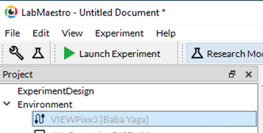
Double-click the VIEWPixx3 device, under “Environment” in the project panel.
The VIEWPixx3 device in LabMaestro
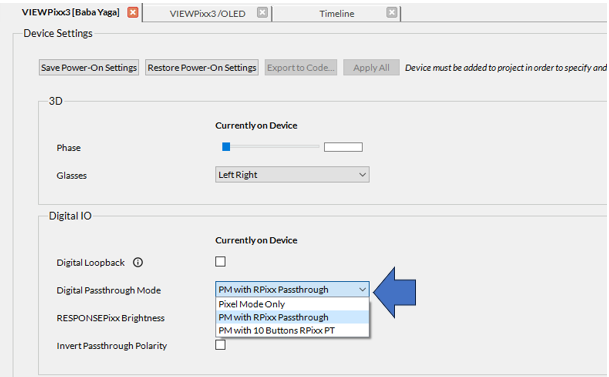
Then in the Device Settings of the VIEWPixx3, use the Digital Passthrough Mode drop down menu to select the Digital Passthrough Mode you wish to enable; the passthrough polarity can be inverted by clicking the “Invert Passthrough Polarity” check box:
The VIEWPixx3 device settings, with Digital Passthrough Mode options