What is bit depth?
Digital images are comprised of millions of picture elements, or pixels, which form the smallest addressable component of an image. On a standard display, a pixel is defined by a triplet of red, green and blue (RGB) colour values. While the exact method by which these RGB components are physically expressed varies by screen technology, at a broad level we can say that the RGB values of a pixel determine the final colour value for that pixel.
Each of the R, G and B components of a pixel represent a separate colour channel. Colour channels have a minimum and a maximum saturation, determined by the screen’s physical properties. The range of colour saturation a screen can show is known as the screen’s gamut.
The full gamut of a given colour channel, from minimum to maximum, can be expressed as a continuous variable ranging from 0 to 1. For hardware reasons, there is a maximum precision with which we can select a colour value from this range. Displays that use an analog video signal, like CRT monitors, can achieve very high precision, which makes them valuable tools in colour research. By contrast, modern digital displays like LCD panels and LED projectors are constrained by the number of bits assigned to each colour channel by the digital video signal and the hardware itself.
Imagine that we have only one bit of data in our video signal for each colour channel. A bit can have two states, either on or off. We will denote these in binary as 0b1 (‘on’), and 0b0 (‘off’). The prefix ‘0b’ indicates a binary number. In a 1-bit colour channel, we have 2^1 states available that we can use to segment the colour gamut.
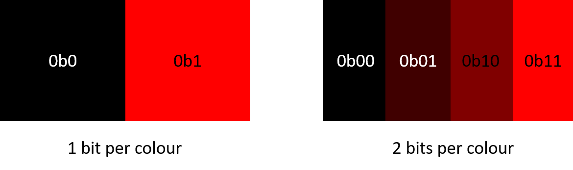
If we add a second bit of data, or bit plane, to our signal, we can describe the colour with greater precision. Now, we have 2^2 unique states available (0b00, 0b01, 0b10, and 0b11), and we can divide our spectrum of possible channel outputs into 4 discrete levels.
The number of bit planes available to define a colour channel is known as bit depth or bits per colour (bpc). Most modern displays are 8 bpc. This means the display can divide the colour space into 2^8 or 256 distinct levels for each of our three colour channels (R, G and B). Some programs represent these steps as a proportion of maximum (e.g., 0-1) or as a raw value (0-255); regardless of the way the value is represented, the level of precision is the same.
It is important to remember that R, G and B colour channels are independent of one another, and combine to form the final colour output. A display with 8 bpc has a total of 24 bits per pixel, and can therefore show over 16 million unique pixel colours.
When we represent values in binary, the position of the bit is important. Bits further to the left in a binary number are considered more “significant” as they have a larger impact on the total value. For example, if we have a 4-bit value like 0b1000 and we flip the bit in the least significant position to create 0b1001, this is equivalent to an increase from 8 to 9 in base 10 counting. If we flip a more significant bit, like 0b1100, we jump from 8 to 12.

The more bit planes we add to our video signal, the more precisely we can define a colour within our gamut. For example, a 10-bit display divides each colour channel into 2^10 or 1024 levels. A 12-bit display has 2^12 or 4096 levels. As the number of bit planes increases, flipping the least significant bit specifies smaller and smaller steps in colour output.
To underscore this point, high-bit-depth displays do not show richer or different colours than a standard 8-bit display. A higher bit depth simply allows you to divide your colour space into finer increments.
So why is this important for vision scientists? Under certain experiment situations, the human visual system is sensitive enough to differentiate between single-step increments in 8-bit displays. Detectable changes are emphasized by the visual system as edges, and this results in a perceptual artifact known as Mach Banding [1]. Mach Banding can be a nuisance for researchers studying colour, luminance and contrast perception. High-bit-depth displays are a valuable tool for avoiding such artifacts, as they divide the display gamut into extremely fine-grained increments that cannot be detected by the viewer.

Unfortunately, adding additional bits to the video signal requires bandwidth, and certain video protocols cannot exceed 8 bpc at full resolution. This is fine for most commercial applications, as modern screens are not capable of showing more than 8 bpc due to hardware limitations. Graphics processors may also employ strategies like temporal or spatial dithering to try and mitigate effects like banding, making them less noticeable.
On the other hand, specialty displays like the VIEWPixx /3D are capable of 10 bpc, and the VIEWPixx and PROPixx can achieve 12 bpc. An analog CRT monitor driven by a DATPixx video I/O hub converting digital video output to an analog signal can reach even higher bit depths.
Therefore, we have the challenge of taking a video protocol restricted to 8 bpc and converting this video into a high-bit-depth image these displays can use. The rest of this series will focus on the different high-bit-depth video modes, how they achieve a high-bit-depth video signal to our displays, and the tradeoffs they make to do so with the limited bandwidth available.
Before continuing, there is one principle that must be highlighted: The final output of any high-bit-depth video mode will depend on the physical capabilities of the screen.
While some of our special video modes allow for up to 16 bpc, this refers to the capacity of the digital video signal. If this signal is passed to a VIEWPixx /3D, the final bit depth of the display will be 10 bpc, because that is the maximum depth the VIEWPixx /3D can physically show. The 6 least significant bits will be ignored because the screen hardware is incapable of showing increments that fine.
When we talk about high-bit-depth modes, we typically describe their bit depth based on the bits available in the digital signal, since this value remains constant across display types. It is good to keep in mind the physical limitations of the screen you are using when assessing what the output of these modes will be.
A primer on colour lookup tables (CLUTs)
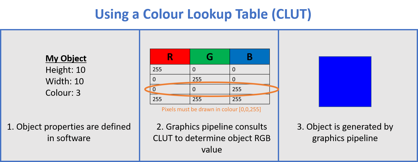
Several of our high-bit-depth modes use a system called colour lookup tables, or CLUTs. These are user-defined, indexable 256 x 3 tables that store high bit depth R, G and B colour information.
When specifying an object’s colour, we use the CLUT row index value in place of our typical R, G and B values. When the video signal is received by our hardware, the appropriate RGB colour values are pulled from the CLUT and assigned to the pixel. This is a useful tool for avoiding bandwidth issues at the software level. Below is an example of an 8 bits per colour CLUT used to assign an object colour.
CLUTs are used for other purposes at different levels within the graphics pipeline. For example, gamma correction may invoke a gamma-corrected CLUT for R, G and B values before passing them on to the display hardware. Dithering or antialiasing by the graphics processor can also alter colour values before they reach hardware (fortunately, these features can usually be disabled).
This is something to keep in mind when using our video modes; if the hardware receives a different value than the intended CLUT index value, you may see very surprising results on your display. In this case, it is a good idea to investigate whether anything else in the graphics pipeline might be altering your colour values before they reach our hardware.
References
[1] Ratliff, F. (1965). Mach bands: quantitative studies on neural networks. Retina. San Francisco, CA: Holden-Day.