Principles of Pixel Mode
In a standard experiment setup with an LCD display, the video signal is passed from your computer’s graphics processing unit (GPU) to the display via a video cable. When the signal reaches the display monitor, multiple frames may be stored in a memory buffer before being shown on screen.
When an image is ready to be shown, a current is applied to the liquid crystal layer of the display, changing the polarization of molecules inside the layer. The extent of this polarization determines how much light passes through each pixel.
This polarization can take time, and so there is a delay before the desired pixel luminance is reached. We refer to this time as the “stabilization” of the pixel. Exact stabilization time depends on the total change of luminance from the previous frame to the current frame, i.e., the total change in polarization required. Here is an example of pixel illumination as it transitions from black to white on a 120Hz display (VIEWPixx in standard display mode), as measured by a photodiode:

Pixel stabilization time from black to white to black, standard LCD display at 120Hz
Our VIEWPixx LCD displays have a special scanning backlight mode so that the pixel does not receive full illumination until it has already stabilized. This leads to better control over the luminance of the display. In scanning backlight mode, pixel illumination profiles look like this:

Pixel stabilization from black to white to black, VIEWPixx LCD displays in scanning backlight mode
VPixx displays also come with an onboard field-programmable gate array (FPGA) chip which intercepts the video signal after it is sent from the computer GPU. In Pixel Mode, the FPGA generates a trigger based on information in the video signal. This trigger is available on the Digital Output DB-25 connector, and the video signal continues to the display.
Because we know exactly when that TTL trigger is sent, and we know the illumination profile of our display, we know the exact temporal offset between the trigger and stabilization of the pixel in the top left corner of our display. On the VIEWPixx displays, this is exactly 6 milliseconds.
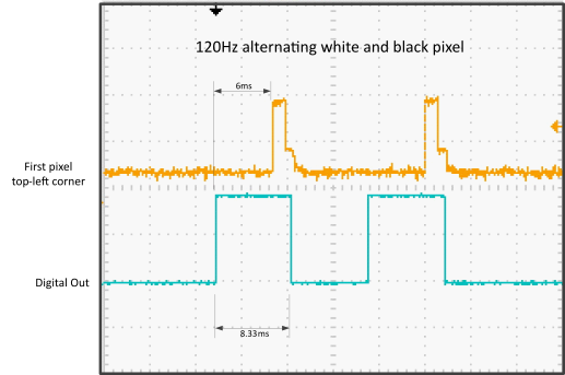
Temporal relationship between top left-hand pixel stabilization on the VIEWPixx in scanning backlight mode, and the rising and falling edge of the digital trigger associated with the same video frame
Using the FPGA we can send a highly precise frame-based trigger to our recording system. We define the content of this trigger so it is informative as well, by changing the colour of that top left pixel and reading the [R, G, B] values as digital outputs. We will cover how this works in the next section.
Pixel Mode was developed for the VIEWPixx /EEG; however, it can also be implemented on other devices like the DATAPixx data acquisition system and the PROPixx controller. For more information about using Pixel Mode with these other systems, please see the section on using Pixel Mode with other devices.