The following VPixx devices are capable of sending and receiving analog signals:
-
All generations of DATAPixx video I/O hub
-
VIEWPixx and VIEWPixx /3D CRT replacement monitors
-
“Full” Controller for the PROPixx 1440 Hz projector
Analog signals are continuous voltages that change dynamically with time, usually between a negative and a positive voltage. Examples of analog signals include EEG, EKG, force plates, eye tracking data and joytsticks. In contrast to digital signals, which have two states (ON and OFF), analog signals are continuous. This makes them ideal for recording fluctuating variables like position, force and energy. Analog signals are also the foundation for audio output.
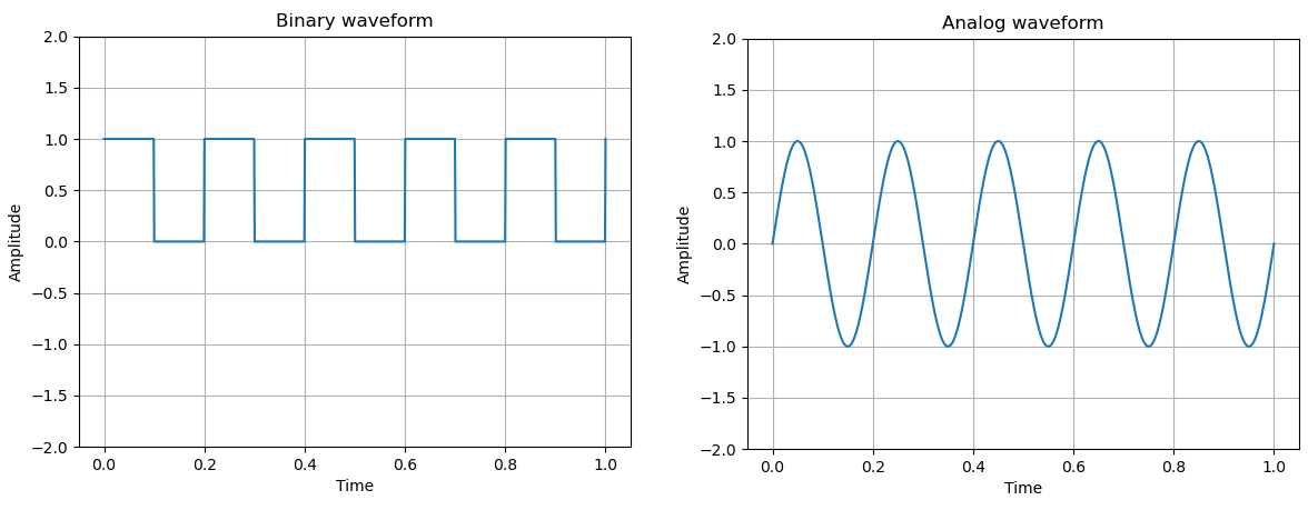
Modern computational systems digitize incoming analog signals with varying precision. Similarly, outgoing analog signals start as complex digital signals which are converted into a pseudocontinuous voltage output. When we use the terms ADC (Analog to Digital Converter) and DAC (Digital to Analog Converter) we are referring to our hardware’s capacity to digitize incoming analog signals and emit analog output, respectively.
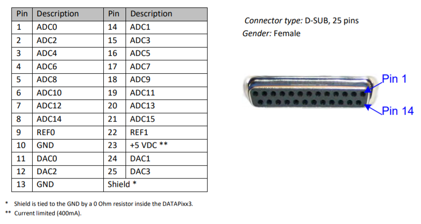
Our hardware includes 16 ADC channels for recording (or 8 differential channels) and 4 DAC channels for emitting analog waveforms. Both have a range of +/- 10V and the converters have a digital precision of 16 bits.
Below are the pin assignments of our DB25 Analog I/O connector.
Properties of the DAC and ADC systems are summarized in the table below:
|
Parameter |
DAC (output) |
ADC (input) |
|---|---|---|
|
number of channels |
4 |
16 (or 8 differential) |
|
converter resolution |
16 bits |
16 bits |
|
voltage range |
+/- 10V |
+/- 10V |
|
sampling across channels |
simultaneous |
simultaneous |
|
frequency mode |
Three modes for playback:
|
Three modes for recording:
|
|
maximum sampling rate |
1 MSPS per channel |
200 kSPS per channel |
On the software side, we manage ADC and DAC channels by configuring writable buffers on VPixx hardware memory that either record incoming signals (in the case of ADC) or store predefined analog waveforms for playback (in the case of DAC).
Buffer management, including recording and playback settings, is performed in MATLAB or Python during your experiment via scheduling. The remainder of this guide will focus on how these schedules are used to configure and operate the analog I/O subsystems.
Navigation