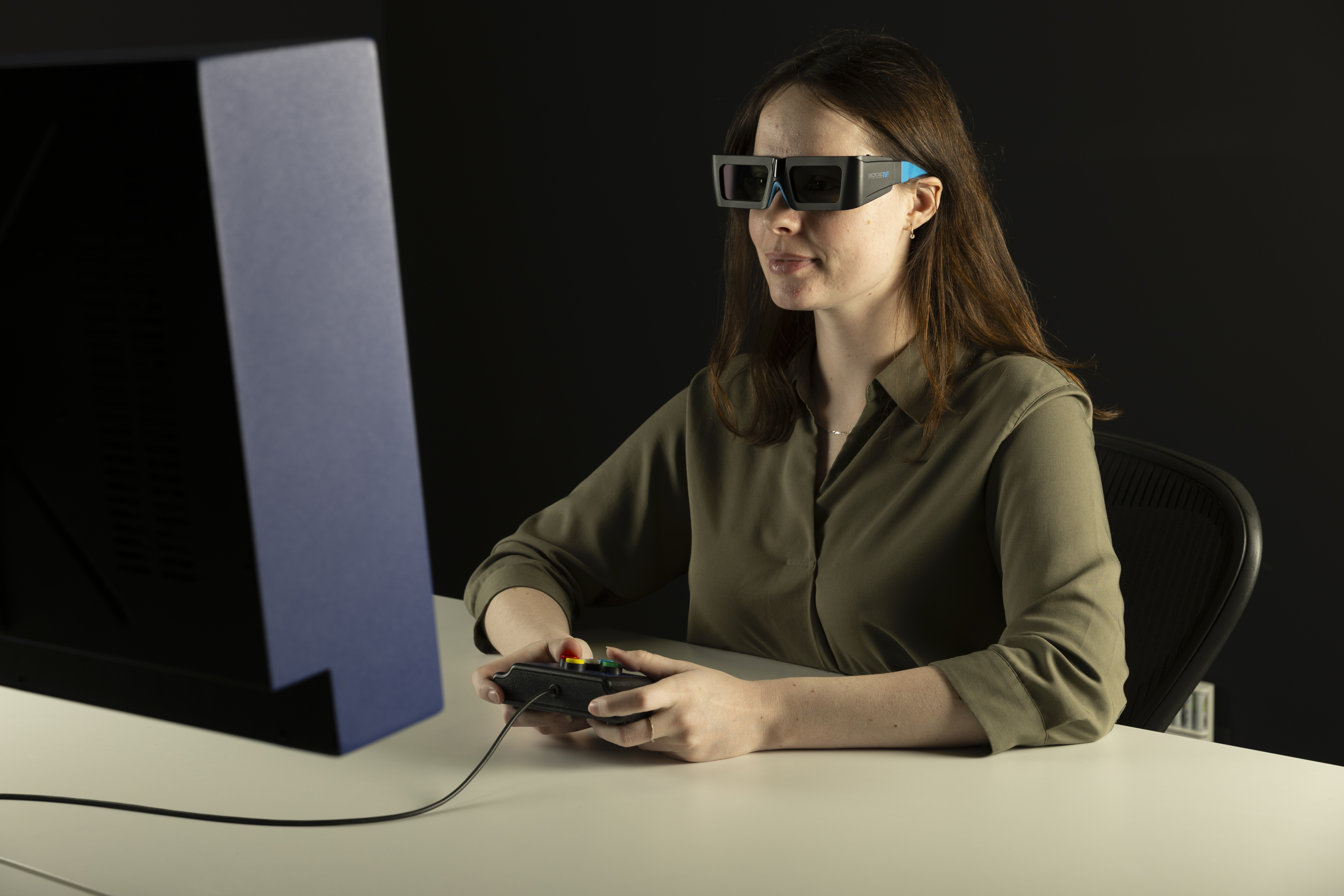
This guide will cover different strategies for using the VIEWPixx /3D and 3DPixx active shutter glasses as a stereoscopic display. Code examples are provided throughout.
A single VIEWPixx /3D can present 3D stimuli up to 120 Hz (60 Hz/eye). Two VIEWPixx /3Ds in a traditional haploscope method (without shutter glasses), support 120 Hz/eye.
There are several methods of presenting 3D stimuli on the VIEWPixx /3D, which we will discuss below. The first three methods use temporal interleaving of left/right images, synchronized with the 3D shutter glasses, on a single VIEWPixx /3D. The final two methods use two VIEWPixx /3Ds in a traditional haploscope-style installation to combine spatially disparate images on the left and right eyes simultaneously.
General instructions for preparing for 3D stimulus presentation
There are several recommendations for initializing the VIEWPixx /3D for stereoscopic presentation, regardless of the specific presentation strategy used. They are:
-
Enable the scanning backlight. The scanning backlight on your VIEWPixx /3D optimizes the display for crisp frame transitions, minimizing ghosting and crosstalk between video frames. This is the ideal mode for 3D presentation. For more details on the scanning backlight, see this section of our guide to the VIEWPixx.
-
Allow a warm-up period of >30 minutes to allow the VIEWPixx /3D to come to a stable temperature. If the screen is not fully warmed up you may see more ghosting in 3D stimuli.
-
Verify the resolution in your display settings. The display settings for each method are shown below. Ensure your operating system display settings use the recommended resolution, and scaling is set to 100%.
|
Method |
Resolution |
Refresh rate(s) |
|---|---|---|
|
Frame-sequential stereo |
1920 x 1080 |
120 Hz
|
|
Stereo blue lines |
1920 x 1080 |
120 Hz |
|
Top-bottom mode (see instructions below) |
1920 x 2322 |
60 Hz |
|
Haploscope modes |
1920 x 1080 |
120 Hz |
-
Restart your experiment software whenever you change the screen resolution. Some software, notably MATLAB, only checks your screen resolution on startup. You need to restart the program to detect a new screen resolution.
-
Use full-screen windows. Borders or smaller stimulus presentation windows may derail synchronization and produce strange results.
-
Avoid maximum and minimum pixel values (e.g., full black, full white). Transitions to these values can show increased crosstalk compared to other values (e.g., 0.9, 0.1).
-
Ensure video mode is set to the default ('C24'). Not necessary for M16 mode.
-
Use LCD3D60Hz mode (older models of VIEWPixx /3D only). For VIEWPixx /3D units sold before 2019, we recommend enabling LCD3D60Hz for improved display output. Examples are shown below. This feature is not required for newer units.
-
Use the correct VESA phase and waveform for your brand of shutter glasses. Not required for haploscope modes. These settings ensure the correct synchronization signal is passed to the glasses. The settings should be implemented at the beginning of your experiment script (see code examples below). See the following details for NVIDIA and Volfoni glasses. For other glasses' manufacturers, we recommend contacting our support team for assistance.
|
Manufacturer |
VESA Waveform |
VESA Phase |
|---|---|---|
|
NVIDIA |
‘NVIDIA’
|
100 |
|
Volfoni |
‘VOLFONI'
|
100 |
-
(Volfoni users) Use the Volfoni loader to adjust the glasses' shutter speed to optimize for brighter stimuli or minimized crosstalk. This optional step can be used to fine-tune the performance of the Volfoni version of the 3DPixx. [Update November 2025: Unfortunately, this tool is no longer available online. Please contact support@vpixx.com for assistance].
Temporally interleaved modes
Temporally interleaved 3D modes present left and right eye images sequentially on a single display. The left and right eye images are paired with a signal emitted by the IR (or RF) emitter driving the active 3D shutter glasses.
The signal indicates to the 3D glasses which shutter should be open on a given frame. Thus the shutter will open for video frames assigned to the corresponding eye, and close for other frames, creating the stereoscopic effect.
In temporally-interleaved 3D, the 3D signal must remain synchronized with the display. If the signal becomes de-synchronized at any point, the wrong image will be presented to the wrong eye.
.png?cb=05321fd6295e54d179ed9f967048f0db)
There are three general methods for temporally interleaved stereo using the VIEWPixx /3D: Frame-sequential stereo, Stereo Blue Lines and Top-Bottom mode.
Frame-sequential stereo (not recommended)
In frame-sequential stereo, images are interleaved temporally. Even and odd video frames are presented to the left and right eye, respectively. Image alternation is controlled manually (e.g., drawing left and right eye images and flipping them one after another) or via dedicated stereo draw buffers alternately sampled during stimulus presentation.
This method is highly vulnerable to frame dropping and 3D desynchronization. We do not recommend this method.
Stereo Blue Lines
Stereo Blue Lines are designed to set the phase of the 3D glasses explicitly. That is, the Blue Lines in the video data tell the glasses which shutter (left or right) should be open for that frame.
In theory, this approach protects against desynchronization caused by dropped video frames. If a frame is dropped, the glasses immediately re-synchronize with the phase specified by the video content.
This logic assumes that the glasses continually self-correct, but our experience with recent shutter glasses (e.g., Volfoni) suggests this is not the case. In practice, with the new glasses, a dropped frame can cause several seconds of desynchronization before the glasses re-synchronize based on Blue Line data.
In light of these findings, VPixx now recommends using Top-Bottom 3D mode as the preferred method for maintaining synchronization with 3DPixx shutter glasses. In this mode (described below), the left and right images are transmitted together as a single “package” at 60 Hz. If a frame is dropped, the entire package (both left and right images) is repeated, preserving alternate-frame stereo presentation.
The following description of Stereo Blue Line mode is retained for historical reference.
Stereo Blue Lines explicitly encode each video frame to target the correct eye. This preserves stereo synchronization even if your system is dropping frames.
Stereo Blue Line is easy to implement:
-
Organize your stimuli as you would for frame-sequential stereo.
-
To assign a frame to the right eye: Set the bottom row of pixels in the frame to an intensity greater than mid-grey [128, 128, 128]
-
To assign a frame to the left eye: Set the bottom row of pixels in the frame to an intensity less than mid-grey [128, 128, 128]
.png?cb=2e88c2d024e9e8577fd65e245b75c49f)
Some software will automate Blue Line generation for you. We generally recommend drawing the line yourself. It is simple and ensures you are formatting your video frames correctly.
‘Blue line’ is the name for historical reasons, but it’s a misnomer. The colour of the line is not important. As long as your pixel values are brighter than mid-grey ([128, 128, 128] in RGB255) it will work as intended.
Top-Bottom Mode
Top-Bottom Mode requires LabMaestro version 1.10 or later.
In Top-Bottom mode, left and right eye images are stacked on top of one another in a single double-height video frame with a blank bar between them. This composite frame is passed to our hardware at 60 Hz. The hardware deconstructs and presents the left and right eye images sequentially (1920 x 1080 @ 120 Hz).
.png?cb=0119eff8f0ef3a256eae5e07caa569eb)
This mode was originally designed for use with 3D stimuli designed in Unity and Unreal game engines. However, it may be useful for other high-level stimulus-generation software such as PsychoPy Builder. Because this mode receives left and right eye images on the same video frame from the GPU, there is no risk of desynchronization of 3D. Occasional frame drops are not likely to be visible.
Configuring your display for Top-Bottom Mode
-
Connect the VIEWPixx /3D to the stimulus computer via USB and video cables. Power on the monitor.
-
Open the LabMaestro application.
-
Locate the VIEWPixx /3D in your Environment, on the left-hand side Project Panel. Double-click on the display to open the Device Settings.
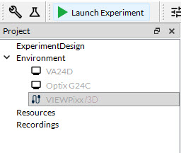
-
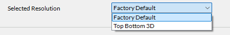
At the bottom of the Device Settings, set the Selected Resolution to Top Bottom 3D. You will be prompted to restart the display.
-
Change the display resolution in your operating system’s display settings, if necessary. The resolution should be set to 1920 x 2322, and the refresh rate should be 60 Hz.
-
Restart your experiment software. Some software like MATLAB only check for resolution on startup, and need to be restarted to register a new display resolution.
Experiment Examples
PsychoPy Builder example
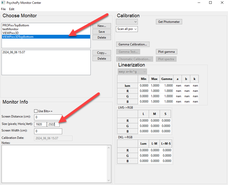
Implementing Top-Bottom mode in PsychoPy Builder is straightforward. We recommend creating a new monitor in the monitor center specifically for Top-Bottom mode to ensure the proper resolution is used. Open the Monitor center, and create a new display with the correct 1920 x 2322 resolution:
You can also insert a custom code block at the beginning of the experiment, to initialize the VIEWPixx /3D settings:
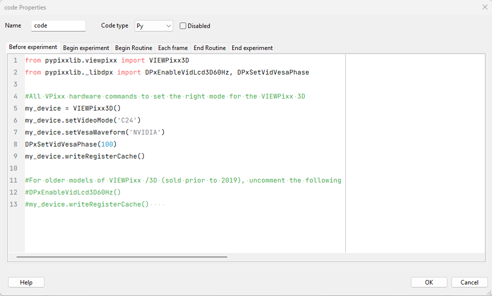
Next, when creating your stimuli, draw images and text as a single double-height image. Images and text directed at the left eye should be placed in the top 1080 pixels of the image, and those directed at the right eye should be placed in the bottom 1080 pixels.
Don’t forget that there is a 162-pixel high blanking interval in the middle of the image. If you are using normalized spatial units, the center of the top (left eye) image is [0, -0.47] and the bottom (right eye) is [0, 0.47], etc.
Unity Example
-
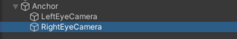
In the Scene view, create an empty GameObject named Anchor. Attach two child cameras, LeftEyeCamera and RightEyeCamera.
-
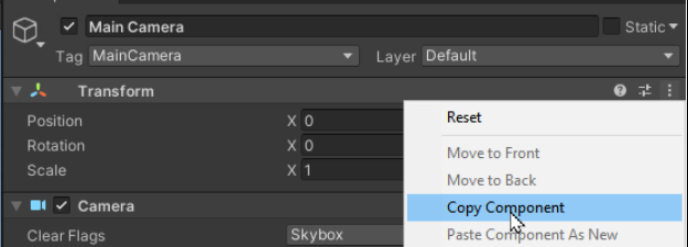
Adjust Anchor’s transform components to match that of the scene’s Main Camera. You can do this by selecting the three dots icon in the corner of the Transform component of the Main Camera, and selecting ‘Copy Component.' Select Anchor, click on the three dots in the Tranform Component, and select ‘Paste Component.’
-
Delete the Main Camera.
-
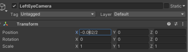
Offset the x position of both the LeftEyeCamera and RightEyeCamera by the 1/2 interpupillary distance each. You may want to write a script to adjust this dynamically for each participant.
-
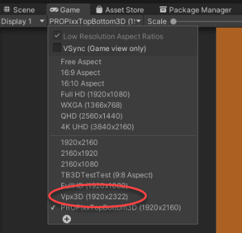
In the Game view, add a new resolution for the VIEWPixx /3D that is 1920 x 2322 pixels.
-
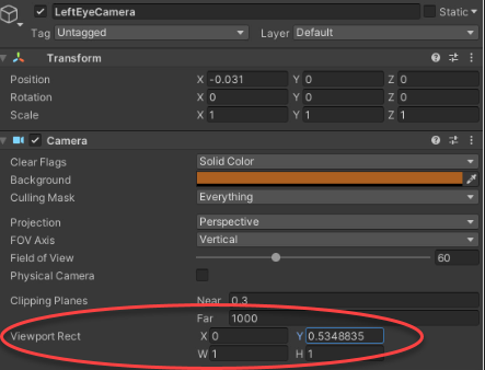
Modify LeftEyeCamera so that it renders only in the top half of the display (excluding the blanking interval between the two eyes). To do this, set the LeftEyeCamera Viewport Rect Y value to 0.5348835.
-
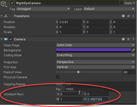
Repeat this process for RightEyeCamera and the lower half of the display. Set RightEyeCamera Viewport Rect H to 0.4651165.
-
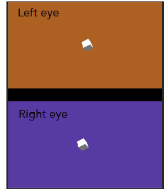
You should now have a Game view with the left and right eye perspectives stacked vertically, and a black band between them. This video will be passed to the VIEWPixx /3D and converted to alternating frame stereo presentation. The black band will not appear in the final stimulus.
Haploscope modes
A haploscope is an optical device that uses a combination of lenses or mirrors to present the contents of two different screens to the left and right eyes simultaneously. While haploscopes can be challenging to align and synchronize, they are a reliable method of presenting stereoscopic images at high speeds (>60 Hz) with absolutely 0 crosstalk.
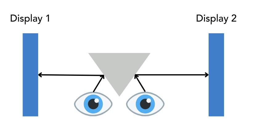
Some researchers elect to use a pair of VIEWPixx /3Ds as the displays in a haploscope in order to take advantage of their excellent timing properties.
It is possible to drive the two displays in the haploscope from the graphics card as unique screens, provided the graphics card is powerful and no frame dropping occurs. However, if perfect synchronization is needed, VPixx has several additional solutions to support haploscopes comprised of our devices, namely Mirrored Greyscale Mode and M16 Mode.
Mirrored Greyscale Mode
Currently, this mode is only available for MATLAB users.
In this case, each display receives the same video but only shows the content of a specific colour channel (in greyscale). This allows for completely synchronized video output with unique content, driven by separate 8-bit colour channels.
The user can specify which colour channel drives which display. For example, the following schematic shows the left eye display driven by the red channel and the right eye by the green channel.
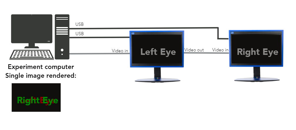
To enable this mode, you must assign unique names to your two VIEWPixx /3Ds to be able to configure them individually in software commands. Next, you must daisy-chain the video output from one VIEWPixx /3D to another to ensure both displays use the same video signal. The steps are outlined in detail below:
-
Connect the first VIEWPixx /3D to your PC via USB cable
-
Open the vputil command line utility and assign the display a unique name via the dn command. For example, ‘dn LEFT’
-
Disconnect the VIEWPixx /3D
-
Repeat steps 1-2 for the second VIEWPixx /3D
-
Re-connect the first VIEWPixx /3D. You should now have both monitors connected to your PC via USB.
-
Connect video input of one VIEWPixx /3D to your PC graphics card. It does not matter which one.
-
Connect the video output from this VIEWPixx /3D to the video input on the second VIEWPixx /3D monitor (see image above).
-
Open MATLAB and configure the displays
If you are using other VPixx functionalities (e.g., digital inputs) make sure you run the SelectDevice command to target the correct monitor, before implementing any calls to the hardware.
To set a VIEWPixx /3D to use a specific colour channel as greyscale, use the command:
Datapixx('SetVideoGreyscaleMode', mode);
Where the following modes are available:
0: Disable greyscale mode, and present normal RGB colors.
1: Present greyscale image defined by red color channel.
2: Present greyscale image defined by green color channel.
3: Present greyscale image defined by blue color channel.
M16 Mode
If you need some colour in your stereoscopic images, you can also use M16 mode. M16 is primarily a high bit-depth mode and concatenates the 8-bit R and G channels to form a 16-bit greyscale that is passed to both the main display (connected to the GPU) and a console display (chained to the main display’s Video Out port). On the VIEWPixx /3D hardware, this 16-bit value is reduced to 10 bits per colour output. See our guide to high-bit-depth modes for more details.
In M16, the console display is NOT connected to your PC, but to the Video Out 2 on your main display. Your PC will not detect the console as a display. By default, the console display will show a copy of the main display.
In M16, the blue colour channel indexes a colour lookup table (CLUT) defined by the user. The user can specify two 256x3 CLUTs for the main display and console. A single value is used to index both.
CLUT values can range from 0-1, with a resolution of 16 bits per colour. The 4 least significant bits will be ignored by the hardware.
Let’s consider a simple example. In M16 mode, I create two CLUTs. In the Main Display CLUT, row 1 is full blue (0,0,1). In the Console CLUT, row 1 is full white (1,1,1). I draw some text and assign it the value (0,0,1) which points to the first row of the CLUTs.
DrawFormattedText(windowPtr, "Hello", 'center', 'center', [0,0,1]);
Screen('Flip', windowPtr);
.png?cb=35cd3a1bc09bbe9c32bf23d1a77f2023)
You can also define a “transparency” colour. The display will ignore this colour if it appears in the indexed row of the CLUT. Assuming we make full blue our transparency, this is the output.
.png?cb=415cfd6e02e391b95ec2ed0fc93b7f57)
The limitation of this method is the available colour space on a given frame. If you need to use transparencies and draw unique colour content to each display, this further limits the available rows in the table.
Some researchers get around this limitation by regularly updating their colour lookup tables (e.g., between trials). However, a single image could not contain a rich colour scene unique to one display.
Blending, interpolating and antialiasing can cause strange results when using CLUTs. It is best to avoid these in our high bit depth modes like M16. See What is Pixel Identity Passthrough? for more details.
On Windows, due to PTB’s scaling methods, row 1 is ignored. Row 2 is indexed as 1, Row 3 as 2, etc. The MATLAB example below demonstrates this.
Summary
In this VOCAL, we covered some general recommendations for using the VIEWPixx /3D as a stereoscopic display, and gave explanations and demonstrations of some methods for implementing 3D stimuli. The methods discussed in this guide are summarized in the table below:
|
|
Description |
Maximum Refresh |
Best Used For |
|---|---|---|---|
|
Temporally interleaved modes (single VIEWPixx /3D and 3DPixx active shutter glasses) |
|||
|
Frame-sequential stereo |
Temporally interleave left/right eye images |
Up to 60 Hz/eye |
Not recommended |
|
Frame-sequential stereo with Blue Lines |
Temporally interleave left/right eye images, blue line used to maintain synchronization of shutter glasses |
Up to 60 Hz/eye |
No longer recommended (see section) |
|
Top-Bottom mode |
Left and right eye images stacked in a double-height window; shown sequentially on display |
60 Hz/eye |
3D applications where video must be robust against desynchronization; ideal for high-level stimulus generation (e.g., Unity, PsychoPy Builder) |
|
Haploscope modes (two synchronized VIEWPixx /3Ds) |
|||
|
Mirror greyscale mode |
Greyscale mode where left and right eye displays are mirrored, and content is driven by different colour channels (converted to greyscale output) |
120 Hz/eye |
Perfect display synchronization with no crosstalk |
|
M16 mode |
Same video signal is duplicated on both displays via console output. Colour lookup tables and transparencies used to present unique content on each display. |
120 Hz/eye |
Perfect display synchronization with no crosstalk, limited colour |