The TRACKPixx3 can stream up to four analog output channels directly to your neurophysiological recording system via the Analog I/O port on the back of the DATAPixx3 control unit. The advantages of streaming analog eye signals are:
-
Extremely short latencies between eye movements and streamed data (~1.7 ms)
-
Permits a single recording interface for neurophysiological data, gaze data and digital triggers
-
Can be used in conjunction with a conventional TRACKPixx3 schedule for more comprehensive offline analysis, if needed
This short guide shows how to configure TRACKPixx3 analog streaming output.
The analog I/O interface
In a conventional TRACKPixx3 setup, the TRACKPixx3 is connected to the DATAPixx3 control unit via a power cable and fibre optic link.

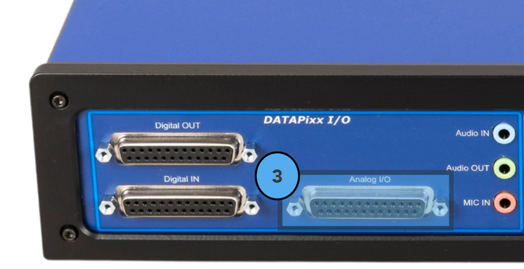
The DATAPixx3 control unit has several ports on the back, including a DB-25 analog I/O interface, shown in the image below. This port can be connected to your neurophysiological recording system and used to stream analog eye-tracking data.

If you require a custom cable or a breakout box to connect this port to your recording system, please see our cabling solutions product page or contact our support team. Do NOT connect third-party cabling to our hardware without being certain of the cable wiring; this could irreparably damage your hardware.
There are four digital-to-analog converter (DAC) output channels on the analog I/O connector. The pin assignment is as follows:
|
Channel |
Pin |
|---|---|
|
GND |
10 |
|
DAC0 |
11 |
|
DAC1 |
24 |
|
DAC2 |
12 |
|
DAC3 |
25 |
|
GND |
13 |
These channels each have a range of ±10 V and 16-bit resolution. The maximum playback rate is 1 MSPS per channel. For full port specifications, see our DATAPixx3 product page.
The streaming capacities listed above are based on the DATAPixx3 output. Your analog receiver will have its sampling rate and resolution, which may be lower. If this is the case, you may notice some loss of precision (e.g., if your receiver only supports 8-bit resolution). Be sure to investigate the capabilities of your receiver and interpret your streamed data accordingly.
Channel options and how to interpret them
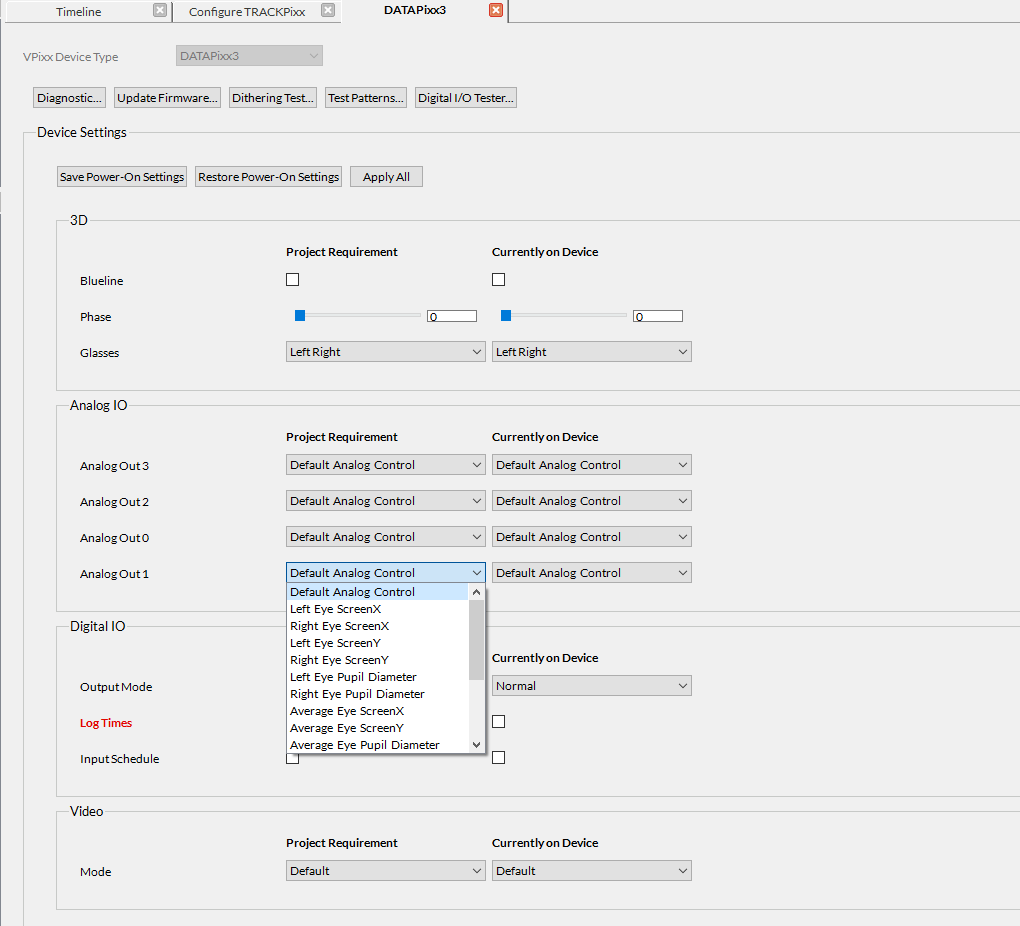
There are 4 channels dedicated to streaming analog data from the TRACKPixx3. Each channel can be independently configured to stream unique data. There are 16 channel configurations to choose from, which are described below.
If you have a DATAPixx3 purchased after September 2023 or an older DATAPixx3 Full, you can also configure one or more DAC channels for a custom-defined analog output schedule (e.g. an audio waveform). See this guide for more details.
|
Option number |
Name |
Description |
Conversion |
|---|---|---|---|
|
0 |
Default schedule-controlled analog |
Default method of controlling analog outputs |
N/A |
|
1 |
Left eye screen X |
Calibrated left eye x position in screen pixels, where (0,0) is the center of the screen |
GazeX = Voltage × 819.670 pixels/V |
|
2 |
Right eye screen X |
Calibrated right eye x position in screen pixels, where (0,0) is the center of the screen |
GazeX = Voltage × 819.670 pixels/V |
|
3 |
Left eye screen Y |
Calibrated left eye y position in screen pixels, where (0,0) is the center of the screen |
GazeY = Voltage × 409.575 pixels/V |
|
4 |
Right eye screen Y |
Calibrated right eye y position in screen pixels, where (0,0) is the center of the screen |
GazeY = Voltage × 409.575 pixels/V |
|
5 |
Left eye pupil diameter |
Left eye pupil diameter in camera pixels |
PupilSize = Voltage × 51.190 pixels/V |
|
6 |
Right eye pupil diameter |
Right eye pupil diameter in camera pixels |
PupilSize = Voltage × 51.190 pixels/V |
|
7 |
Average eye screen X |
Average calibrated x position of the left and right eyes in screen pixels, where (0,0) is the center of the screen. Note that if one eye fails to track, the data will be equal to the eye that is successfully tracked. If both eyes fail to track, the output will be -5.00 V. |
GazeX = Voltage × 819.670 pixels/V |
|
8 |
Average eye screen Y |
Average calibrated y position of the left and right eyes in screen pixels, where (0,0) is the center of the screen. Note that if one eye fails to track, the data will be equal to the eye that is successfully tracked. If both eyes fail to track, the output will be -5.00 V. |
GazeY = Voltage × 409.575 pixels/ |
|
9 |
Average eye pupil diameter |
Average left and right eye pupil diameter in camera pixels. Note that if one eye fails to track, the data will be equal to the eye that is successfully tracked. If both eyes fail to track, the output will be -5.00 V. |
PupilSize = Voltage × 51.190 pixels/V |
|
10 |
Blink detection flag |
Whether the blink detection flag is raised |
-2.00 V = Left eye blink
|
|
11 |
Left eye raw X |
The value of the X component of the vector between the center of the pupil and the corneal reflection for the left eye in camera pixel space. Used for custom image processing. |
Raw = Voltage × 12.799 pixels/V |
|
12 |
Right eye raw X |
The value of the X component of the vector between the center of the pupil and the corneal reflection for the right eye in camera pixel space. Used for custom image processing. |
Raw = Voltage × 12.799 pixels/V |
|
13 |
Left eye raw Y |
The value of the Y component of the vector between the center of the pupil and the corneal reflection for the left eye in camera pixel space. Used for custom image processing. |
Raw = Voltage × 12.799 pixels/V |
|
14 |
Right eye raw X |
The value of the Y component of the vector between the center of the pupil and the corneal reflection for the right eye in camera pixel space. Used for custom image processing. |
Raw = Voltage × 12.799 pixels/V |
|
15 |
Left eye saccade & fixation flag |
Status of the saccade and fixation flags for the left eye |
-2.00 V = Saccade
|
|
16 |
Right eye saccade & fixation flag |
Status of the saccade and fixation flags for the right eye |
-2.00 V = Saccade
|
Configuring your analog output channels
Click on the section below to see how to configure TRACKPixx3 analog output using LabMaestro and our API tools.
Summary
The TRACKPixx3 can stream four independent channels of eye-tracking-related data to your neurophysiological recording system via the analog I/O interface on the back of the DATAPixx3. Custom cabling or a breakout box is generally required. Channels can be configured and support 16 unique options, including custom analog waveform schedules. These data can then be converted back into their relevant coordinate systems using the conversion formulae provided in this guide.
Note that for testing purposes, ADC loopback (e.g., as shown here) cannot record DAC streamed output from the TRACKPixx3. You must use a physical hardware loopback cable, an oscilloscope or your neurophysiological recording system to measure streamed TRACKPixx3 output.
