Consequences for VPixx synchronization tools
Several of VPixx’s synchronization tools rely on a one-to-one mapping of pixel value assignment and screen output. Dithering can disrupt this mapping and cause these tools to stop working properly. Three major tools affected by dithering are Pixel Sync, Pixel Mode and hardware colour lookup tables (CLUTs).
Dithering and Pixel Sync: -1010 and timeout errors
VPixx’s register-based synchronization system allows users to change multiple device settings in a single write command to VPixx hardware. All setting changes are enabled simultaneously, allowing users to send triggers, begin audio playback, commence data acquisition and more, all at the same time.
Register writes and updates can optionally be locked to the onset of specific events in the video signal. The ‘RegisterWritePixelSync’ (write command) and ‘RegisterWriteReadPixelSync’ (update command) indicate that the next settings change should occur when a custom sequence of pixels, or sync trigger, is detected by the acquisition system.
Steps to write to the register via Pixel Sync. A register update works similarly, but also blocks all subsequent code until the sync trigger is detected and the device returns its current state.
When the experiment software invokes a Pixel Sync command, the VPixx device immediately enters a busy state and waits until it detects the sync trigger in the video signal.
If the command is an update, it will block all subsequent lines of your code until either the sync trigger is detected or the system times out. Then, the device will return its status and the code can continue.
However, if the command is write-only, your software is able to continue executing subsequent lines in your script while the VPixx device is busy waiting for the sync trigger or timeout.
While the device is busy, any further attempts to communicate with it (e.g., by additional register writes) will be queued until the device becomes available. Repeated communication attempts can throw a -1010 error in MATLAB, and can even cause your experiment software and VPixx device server to crash.
If your graphics card is dithering output, the sync trigger may be compromised. In this case Pixel Sync will not find its target sync trigger and will proceed to timeout. Not only does this break synchronization, it can also throw errors and crash your software if you repeatedly query the device while it is still busy waiting for timeout.
Psychtoolbox commands that have the format PsychDataPixx(‘ ‘) may invoke Pixel Sync as part of their behaviour. If you are receiving timeout or timing errors in the absence of an explicit Pixel Sync in your experiment code, check to see whether one of these commands might be calling it in their definition.
Dithering and Pixel Mode: Unexpected Trigger Values
Pixel Mode is a method of automatically generating digital TTL triggers. There is an in-depth VOCAL guide to Pixel Mode and how it works here.
In brief, Pixel Mode works by reinterpreting the RGB value of the top left pixel on the display as a 24-bit TTL state. This state is applied to the device’s digital output port, and it remains until the pixel value changes.
Pixel Mode reads the video signal directly. It does not matter what program is used to draw the Pixel Mode pixel, as long as it appears in the right place on the screen. Pixel Mode is a great way to automate frame-accurate TTL triggers with any experiment software and no programming required. You can even use it with PowerPoint!
Steps to send a trigger via Pixel Mode
The consequences of dithering for Pixel Mode can be disastrous. Triggers are based on video output; dithering jitters this output, and so dithering will jitter your trigger values as well. This is particularly bad when the trigger value happens to correspond to a binary representation that is on the cusp of the next significant bit, e.g. from 7 (0b111) to 8 (0b1000). In this case, dithering can cause an entire swath of pins to change state, as the example below demonstrates.
Dithering pixel values by +/-1 can have disastrous effects for Pixel Mode triggers, especially if the pixel value is close to a major change in binary representation of the output. Here, a dither from 127 to 128 sets red 7 high and shuts off all other pins. If your system is not recording from red bit 7, this trigger will be completely missed.
Dithering and Colour Lookup Tables (CLUTs): Colour value reassignments
A CLUT is a list of pre-defined colours that the graphics pipeline consults when drawing images. CLUTs are typically 3-column tables of red, green and blue pixel values. When setting up a display, the user can optionally tell the graphics pipeline to use a specific CLUT to set the final colour output. The CLUT may contain values, for example, that are gamma corrected such that the display’s output will have a linearly increasing luminance.
Once a CLUT is enabled, images are assigned a colour value that corresponds to a row in the CLUT. The graphics pipeline will then generate an image with the RGB colour values listed in that row.
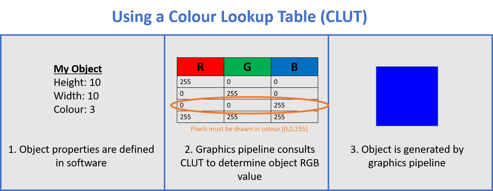
Applying a typical CLUT. In this case, the Object’s colour property specifies the third row of the CLUT as the RGB colour value.
CLUTs can be invoked at multiple levels in the graphics pipeline. They may be implemented in software before the image data is passed to the graphics card, or they may be used by the GPU itself.
Some of VPixx’s special video modes, like M16 mode, make use of custom CLUTs that are loaded directly into our hardware. In this case, the graphics card draws the initial image and passes it to the display. The display hardware then interprets the image’s colour as an index to a CLUT stored on the device, and presents the image with the colour value specified in that CLUT. This strategy allows VPixx displays to overcome bandwidth limitations inherent in the video transmission protocol.
Of course, if your graphics card is dithering output, this poses a problem for hardware CLUTs. You may set your image colour to a specific value, with the goal to index a particular row in the hardware CLUT. If this value is dithered by your graphics card, it will end up pointing to a different row in the CLUT and your image will drawn in the wrong colour.