In our companion VOCAL guide, we demonstrated how to measure the temporal characteristics of pixel illumination on the VIEWPixx /3D using a photodiode and the VIEWPixx /3D’s built-in data acquisition system. The goal of that exercise was to verify the regularity of pixel illumination across video frames and show the effect of the scanning backlight on the pixel illumination profile.
In this VOCAL article, we will use the same approach with our PROPixx DLP projector and its control hub to investigate the time course of the projector’s pixel behaviour. The PROPixx projector supports various refresh rates, summarized in the table below; we report pixel illumination behaviour for several of these refresh rates and two of our specialty sequencers. This guide demonstrates how to take these measurements, with code examples, should you wish to take measurements on your own system.
|
Refresh rate |
Resolution(s) |
Frame duration |
|---|---|---|
|
60 Hz |
1920 x 1080
|
16.66 ms |
|
120 Hz |
1920 x 1080
|
8.33 ms |
|
180 Hz |
1280 x 1024 |
5.56 ms |
|
240 Hz |
1280 x 720
|
4.17 ms |
|
360 Hz |
640 x 1080 |
2.78 ms |
|
480 Hz |
960 x 540 |
2.08 ms |
|
480 Hz (QUAD 4x) |
960 x 540 |
2.08 ms |
|
1440 Hz (QUAD 12x) |
960 x 540 (greyscale) |
0.69 ms |
Digital Light Processing (DLP) Technology
Before describing the methodology used to collect our measurements, we will take a moment to review how DLP projectors work. This will provide context for the DLP pixel behaviour and why it looks so different from LCD pixel behaviour.
Pixel composition
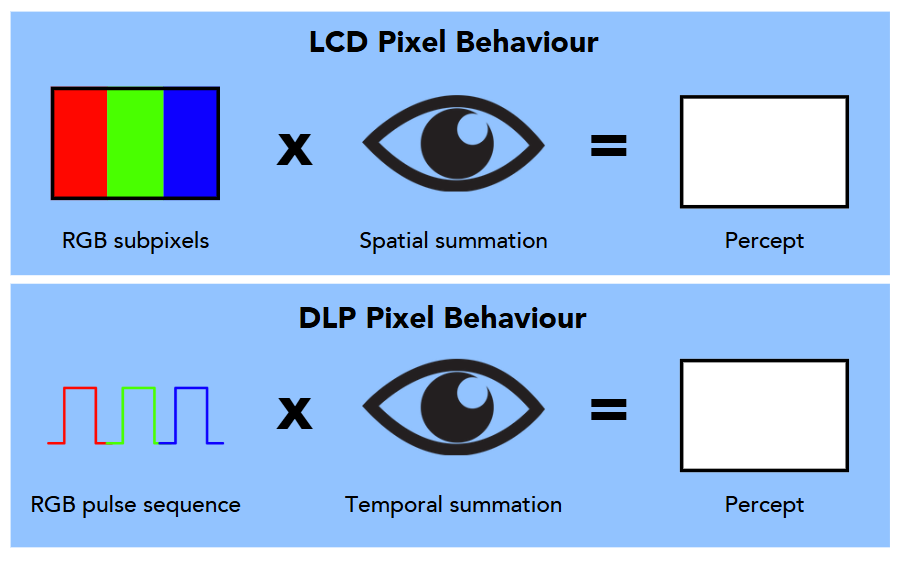
On an LCD monitor, pixels are subdivided into red, green and blue components, usually distributed as vertical stripes. When a pixel illuminates, the liquid crystal molecules allow light to pass through each component in varying amounts. Our eyes spatially sum these components to give us a single percept of the pixel’s colour.
In contrast, DLP technology alternates variable-duration pulses of red, green and blue light called a sequence. Each pixel receives a unique sequence; our eyes temporally sum these pulses into a single solid colour for that pixel.
DLP pixels are not ‘pixels’ in the traditional sense, but we treat them as such in code, so it’s helpful to think of them this way.
To learn more about DLP projection technology, see our VSS2020 recorded talk: Advanced vision research paradigms with the PROPixx high refresh rate projector (V-VSS 2020).
Characteristic response profile
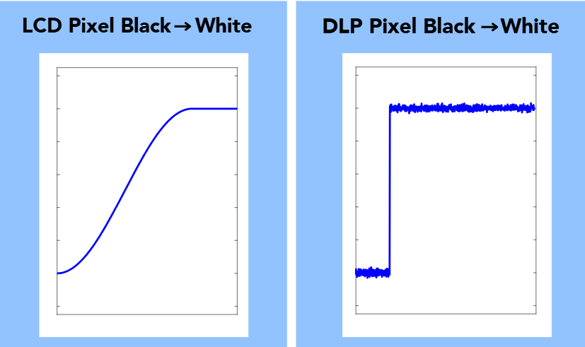
DLPs are much faster than LCDs in terms of their response profile. Consider a luminance ramp of a standard LCD pixel transitioning from black to white vs. a DLP pixel:
A few things to notice about these two traces:
-
LCDs are slower, and the transition between values is a ramp. A scanning backlight can help impose crisp pixel transitions on this profile and eliminate some artifacts associated with slow pixel transition times.
-
DLP projectors have a near-instantaneous response time. Their luminance trace also has characteristic ‘noise’ that reflects the subframe RGB pulse sequence. Very high-temporal-precision photodiodes may be able to map these subframe pulses in their entirety; many commercial photodiodes are too slow and show the sequence as a bit of jitter in the luminance value.
Pixel behaviour across the display area
LCD panels operate on a row-by-row basis and begin illuminating as soon as the display receives the first line of the video signal. As the rest of the video signal is received, successive rows of the display update. This process creates a small but measurable temporal offset between horizontal rows of pixels on the monitor. Our Pixel Behaviour Simulation in our companion guide for measuring VIEWPixx /3D and /EEG performance visualizes this offset.
In contrast, the PROPixx projector waits for an entire frame’s worth of video data to be received, and then the entire display updates simultaneously. Therefore, a full-frame transition from black to white on a DLP display will have the exact same temporal response profile, no matter where on the display it is measured.
Measuring Pixel Responses on the PROPixx
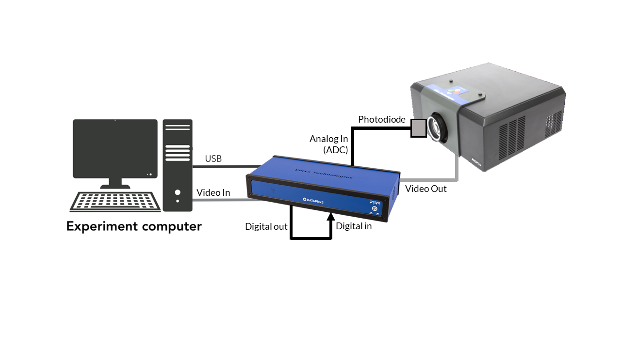
The PROPixx integrates with a data acquisition system and video I/O hub as a control unit (at the time of this publication, it is the DATAPixx3). The control unit is equipped with analog, digital, and audio I/O channels, which can be synchronized with video output to the projector. The digital output can be configured through Pixel Mode to automatically generate a signal when the I/O hub receives a new video frame. We will use a physical cable connecting the digital output to the digital input on the I/O hub to record the time of these signals on VPixx hardware; this is known as a hardware loopback.
To measure the response profiles of luminance changes on the PROPixx, we will use a photodiode mounted directly in front of the projection lens. The photodiode converts photons of light into electrical currents; by coupling this with a trans-impedance amplifier, the current can be converted to changes in voltage, which are recorded on the I/O hub’s analog input (or ADC).
In sum, we configure the hardware to send and receive a signal when the video data is received while also measuring the output of the photodiode. With this simple method, we can capture both video signal and display behaviour on the same hardware clock, with microsecond precise timing.
The stimuli we display for our photodiode measurements are simple alternations between white and black frames at the PROPixx’s set refresh rate.
Displaying alternating white-and-black frames at various “real-time” refresh rates on the PROPixx
Code
Below is MATLAB/Psychtoolbox code for displaying alternating white and black frames while sending Pixel Mode triggers at the start of each frame, at either the native refresh rate (120Hz) or one of the projector’s real-time high refresh rates (180Hz, 240Hz and 480Hz). For instructions on how to set the PROPixx in one of these real-time refresh rate modes, see the following resource: Real time refresh rates.
The following code also shows how to configure and record Pixel Mode triggers and photodiode output. Feel free to copy and modify this code to reflect your own visual stimulus properties.
Results
When we plot the photodiode trace and the Pixel Mode triggers for each frame, we can see that the Pixel Mode trigger is recorded one full frame ahead of the photodiode trace changing. Again, this reflects that Pixel Mode triggers are sent as soon as video data for the frame starts transmitting, while the display does not physically update until transmission of the video data has finished. This process takes one frame (e.g., 8.33 ms at 120 Hz).
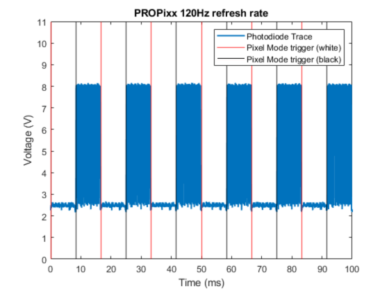
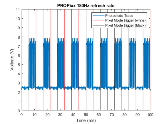
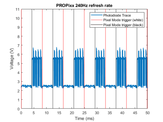
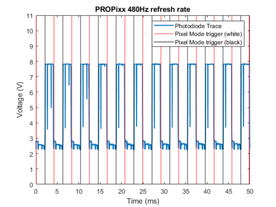
Note that the temporal profile of luminance changes is highly regular.
To drive the PROPixx at high speeds, your graphics card must reliably output frames at the specified rate. Otherwise, you will see clear evidence of frame dropping, in which a video frame’s contents are repeated (see: https://docs.vpixx.com/vocal/a-scientist-s-guide-to-frame-dropping ). If your measurements suggest this is happening, try a slower refresh rate, use a different PC, or use one of our specialty sequencers described below.
Displaying alternating white-and-black frames with the PROPixx’s QUAD4X (480Hz) and QUAD12X (1440Hz) sequencers
In this section, we will measure the behaviour of two of PROPixx’s special sequencer modes for displaying high refresh rates:
In these special sequencer modes, the PROPixx receives full HD video frames (1920x1080) at a rate of 120Hz, and the sequencers “break down” each frame into subframes, which are displayed sequentially to achieve a higher refresh rate. This approach has the advantage that it can overcome the limitations of even entry-level graphics cards and reliably show images at super-high speeds.
To display alternating white and black frames in QUAD4X and QUAD12X, we can send the PROPixx a half-black, half-white frame at 120Hz (every 8.33 ms). QUAD4X will break this down into four quadrants, shown sequentially; QUAD12X will show each quadrant for red, green and blue colour channels individually (as 8-bit greyscale).

Because we are sending the identical frame, above, at 120Hz, only a single Pixel Mode trigger (white [255 255 255]) would be sent; i.e. the top-left pixel in the frame is white. For purposes of illustration, we draw a black pixel on the top-left corner of every even numbered frame, in order to send and record a Pixel Mode trigger on each frame.
Code
Below is MATLAB/Psychtoolbox code for displaying alternating white and black frames, using the Quad4x and Quad12x sequencers, while sending Pixel Mode triggers at the start of each 120Hz frame:
Results
As mentioned in the previous section, the PROPixx does not display a new frame until all of the pixel data for that frame has been received. This is also the case when using the special high-refresh rate sequencers (QUAD4X and QUAD12X).
Pixel Mode triggers execute based on the composite image data sent to the hardware at 120 Hz, i.e. before the image has been broken down. This lets your hardware use the full 24-bit colour signal when sending TTL data, but it also means triggers have a maximum transmission rate of 120 Hz (composite image transmission rate). To determine the timing of specific frames in the 4-frame or 12-frame sequence, simply use the formula:
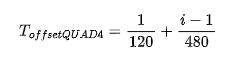
For QUAD4X, where ToffsetQUAD4 is the delay in seconds between trigger start and the pixel transition for the ith frame in the 4-frame sequence, i.e. i takes on the values 1-4; and
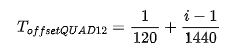
For QUAD12X, where ToffsetQUAD12 is the delay in seconds between trigger start and the pixel transition for the ith frame in the 12-frame sequence, i.e. i takes on the values 1-12.
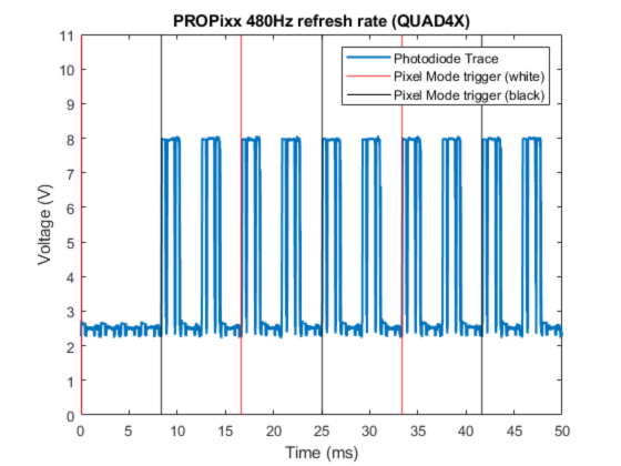
In the trace below, you can see that precisely 8.33 ms after the trigger, the PROPixx begins displaying the first white subframe and then continues alternating between black and white at 480Hz, or 1440Hz:
Once again, you can see the regularity of the temporal profile of the PROPixx’s luminance output, illustrating its fully deterministic timing, as well as the near-instantaneous pixel rise and fall times. This consistency allows for straightforward extrapolation of the timing of individual frames on the display.

Summary
In this guide, we have demonstrated how the PROPixx I/O control hub and a photodiode can be used to measure the pixel response profile of the projector at various real-time refresh rates or with our special sequencers. We characterize the pixel response profile for a select number of these refresh rates and modes, and provide code should you wish to replicate these results with your own equipment.
Some key takeaway points from this guide are highlighted below:
-
For pixel output, DLP projectors rely on the temporal summation of R, G, and B light pulses within a single frame called a sequence. This contrasts with LCD technology, which uses spatial summation of R, G, and B colour strips that illuminate simultaneously.
-
DLP pixel transitions are extremely fast and resemble a square wave function with some “jitter” reflecting subframe sequencing, depending on the temporal resolution of the photodiode.
-
DLP pixels are highly regular and uniform in their behaviour. The projector waits for all video data for a given frame to be received, then updates the entire display simultaneously. This process takes one full frame to occur (e.g., 8.33 ms @ 120 Hz)
-
Video-based triggers that execute at the start of video signal transmission (e.g., Pixel Mode) will lead PROPixx pixel transitions by precisely one video frame. This reflects the delay described in the last point.
-
Specialty sequencers like QUAD4X and QUAD12X that “break down” a composite image have similar temporal characteristics as real-time refresh rates, just faster. Video-based triggers execute based on the start of the transmission of the composite image; the timing of individual frames within a sequence can be mathematically derived and experimentally demonstrated.