This walkthrough aims to familiarize TRACKPixx3 users with the purpose and implementation of our TRACKPixx3 gaze calibration. In this guide, we will cover the following:
-
What is calibration, and why do we do it?
-
Different software tools available for calibration
-
Left vs. right eyes – from whose perspective?
-
The calibration procedure, step-by-step
-
What is a “good” calibration? When to accept, and when to recalibrate
-
Drift checks and intermittent recalibration in long studies
What is eye tracker calibration, and why do we do it?
There are many eye-tracking technologies available on the market, each with advantages and disadvantages. The TRACKPixx3 is an infrared video-based eye tracking system, a popular noninvasive method for measuring gaze and eye movements.
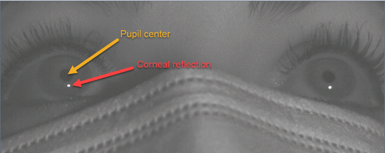
The basic premise of infrared video-based eye tracking is as follows. A special illuminator beams infrared light directly into the participant's face. This is not visible to the participant, however, a specialized infrared camera can record the illumination of the participant's face and eyes in infrared light. A high-speed image processing algorithm is applied to this video recording. The algorithm identifies two key landmarks in each eye: the center of the pupil, which is non-reflective in infrared, and the reflection of the light off of the cornea (also known as the first Purkinje image), which is very bright.
The relationship between these two landmarks, as they appear in the camera feed, changes systematically as a participant looks around the display:
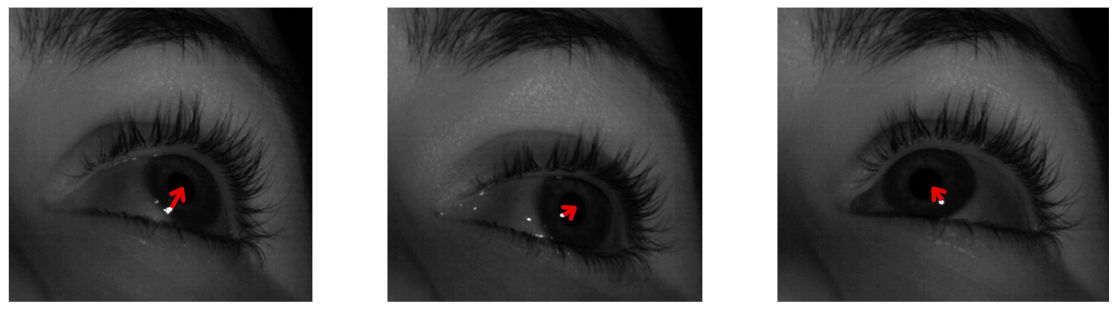
The exact nature of this change depends on a lot of variables, including:
-
the angle of the camera/lamp
-
the position of the participant
-
individual morphology of the eye
-
which eye is being tracked
Therefore, it is necessary to build a unique model of this change for each participant, and each eye, each time they or the camera take on a new position. Once we have created this model, we can apply it to new images of the eyes and infer with high accuracy and precision where they are currently looking.
This is the goal of calibration: to generate a model of the pupil-corneal vector change across the display, so that it may then be used to interpret real-time vector data from the camera.
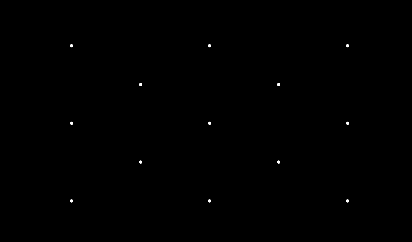
The model is built in two steps. First, we present a series of targets to our participants. These targets are strategically placed across the display to cover the full range of eye movements anticipated in the study. Here’s an example of our classic 13-target layout for human participants:
During the calibration, we assume the participant is following instructions and looking at the target currently visible on the display. We measure the raw vector between the pupil center and corneal reflection in the camera image and store this data for that specific location on the screen.
Once we have vector data for our target locations, we compute a polynomial function that best accounts for the data given the target locations. This becomes our working model.
An important part of the calibration procedure is data validation. We apply our working model to the original data and present the error between the true target location and the location of gaze as computed by the working model.
The experimenter has to decide at this point whether the amount of error in the fit is acceptable, or whether we must reject the working model and re-calibrate to generate a new one.
Different software tools for calibration
Currently, we offer three different methods of calibrating the TRACKPixx3:
-
via the LabMaestro software from VPixx
-
via our Python API
-
via our MATLAB/Psychtoolbox API
All three methods follow the same general process and logic. They present targets, collect data, build a model, present the results of the data validation, and wait for the experimenter to accept or recalibrate. All three methods offer the possibility of customizing the calibration procedure to suit your research needs.
We will provide examples from all three methods throughout the rest of the guide.
This documentation is being released early with the Python examples included. LabMaestro and MATLAB calibration routines are currently being updated, and screenshots/examples will be shared soon.
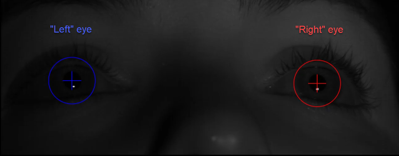
Left vs. right eyes – from whose perspective?
Depending on your experiment layout, the camera may face the participant, or record from a mirror (some NHP installations; MRI installations). This means that in some cases the camera’s perspective is inverted from the participant’s perspective, while in other cases it is not. So when we say ‘left eye,’ whose left are we talking about?
In all TRACKPixx3 tools, the directions ‘left’ and ‘right’ refer to the sides of the camera view as it appears on the display. It is good to keep in mind, especially during troubleshooting, that these labels may not correspond to the left and right eyes from your participant’s point of view.
Best practices for your eye-tracking setup
Many calibration issues can be traced back to problems with bad camera placement and the eye-tracking environment, Before you begin calibrating, consider some general best practices for your setup:
For short-distance tracking (tabletop, MEG, NHP)
-
The camera should be between 40-70 cm from the participant’s eyes
-
The camera should be as close to the bottom of the screen as possible
-
Large screens (>35 degrees of visual angle) are not recommended
-
The participant’s eye height should align with the center of the screen
For long-distance tracking (MRI)
-
The camera should have a clear line of sight to the head coil mirror
-
The head coil mirror should be first-surface (aka front-surface) to avoid internal reflections
You do not need to follow these recommendations to the letter. If your calibration results look good, don’t worry too much about the exact screen size or camera placement.
However, if you are having trouble calibrating, these guidelines are a good place to start when troubleshooting how to improve your results. You can also see our guide Common Eye Tracking Problems and How to Solve Them.
The calibration procedure, step-by-step
This section describes the general steps of the calibration procedure.
Step 1: Configuring the tracker and the calibration settings
Before launching the calibration, the experimenter must configure the eye tracker and the calibration settings. These settings include properties like the target colour, the number of targets, and which eye you would like to calibrate. Many settings, particularly those related to the tracker (ex, lens type) can be left as their default values. Other settings need to be adjusted for each participant; we will discuss these in the relevant steps below.
Tracker and calibration settings are summarized in Appendix I at the end of this guide. You can also find descriptions of the settings within each calibration tool. For instance, in Python the calibration routine begins with a prompt for approval/modification of settings:
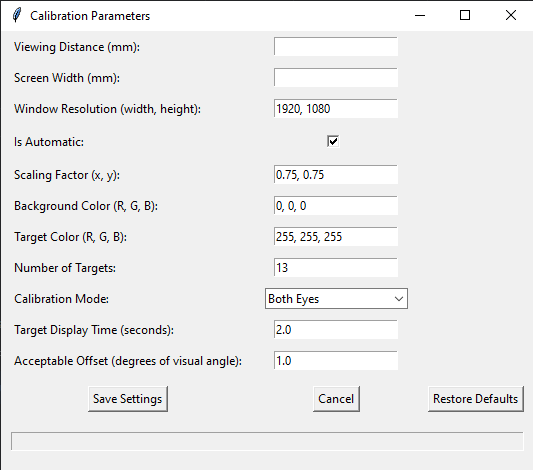
Hovering over the parameter name will show a description of the parameter at the bottom of the GUI.
Once your settings have been configured, you can continue to step 2.
Changing your default settings: In many cases, your experiment setup may have consistent values that differ from the original software defaults. To modify default values in our APIs, you can edit the TPxTools module containing the Calibration Handler class. The relevant section (in Python) looks like this:
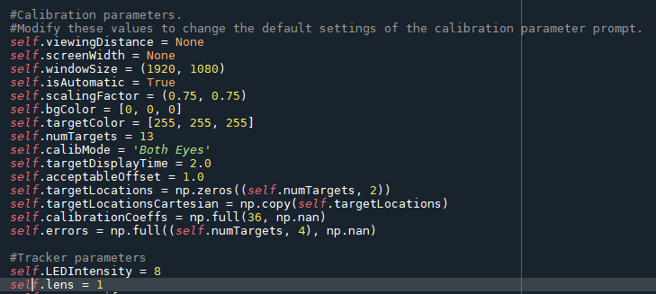
Bear in mind that this will change the values that appear in the GUI on startup, for all users of the TPxTools. You should only set defaults for constants like screen width, that are unlikely to change between experiments.
Step 2: Focussing the camera
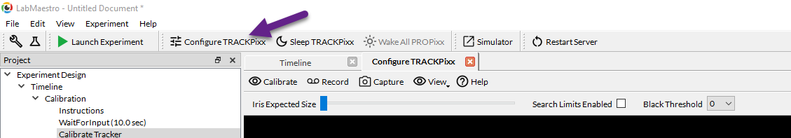
Once your parameters have been set, you can adjust the TRACKPixx3 hardware to focus on your participant’s eyes. In MATLAB and Python, the camera window will appear on the stimulus display as part of the calibration script. In LabMaestro, you can access the camera view by clicking on Setup TRACKPixx in the header menu:
A clear, in-focus image is critical for a good calibration routine. Start by adjusting your participant’s chair and chinrest so they are comfortable.
Next, adjust the tilt of the camera mount such that the camera points at the participant's eyes. You may also need to adjust the camera arm yaw and camera position on the arms. The goal is to angle the camera and the illuminator beam at the participant. Try to avoid any extreme tilts of the camera; if the camera is too low, try raising it or lowering the screen, rather than tilting the camera.
.png?cb=52c00335b0ceb8f8ab78533e80ea8318)
Once the camera image is centred on the face, you can adjust the camera aperture so that the eyes are illuminated. The adjustment ring is the anterior ring on the camera lens.
.png?cb=1112656ff3f51c0059dc370c9987ba63)
Adjust the aperture to 50-60% of the maximum intensity. The image processing algorithm does not need much light to focus, and the smaller the aperture, the larger the depth of field for the focus.
The focus can be adjusted using the posterior ring on the camera lens. Both eyes should be visible and well-defined in the camera view.
.png?cb=1b4173fa0570c4ec181a5f9ac84e61f8)
Next, adjust the iris size so the circles are overlaid on the outer edges of the participant’s iris. This aids the image processing algorithm. In the MATLAB and Python calibrations, the up and down arrow keys adjust the iris size. In LabMaestro, iris size can be adjusted via a slider in the Configure Tracker subheader.
Finally, if your participant wears glasses, you may wish to add search windows to the image. These windows restrict the area in which the image processing algorithm looks for our landmarks. This is particularly useful if the participant has reflective lenses and/or frames, which produce additional bright spots the algorithm may mistake for corneal reflections.
Search windows can be added by clicking the left mouse button and dragging it over the left eye, and clicking the right button and dragging it over the right eye. Clicking the middle button clears the search windows. In LabMaestro, there is a checkbox in the Configure Tracker subheader to enable or disable/clear search limits.
Step 3: Measuring pupil dilation
The pupil is not a perfect circle. The center of the pupil, according to the image processing algorithm, can shift as the pupil dilates and contracts. To account for this shift, we record the drift of the pupil center across a brightness-induced pupil dilation and factor this into the subsequent gaze model.
The effect of the pupil calibration step depends on several factors, including the individual morphology of the participant’s eye and the likelihood of pupil size changes during your experiment. In general, this step is not required to achieve good tracking results for a majority of studies.
The pupil dilation calibration routine is currently undergoing internal development. This section will be updated with the pupil calibration steps once development is complete.
Step 4: Gaze point calibration
Once the tracker is in focus, it is time to present our targets. Below is a demonstration of the default 13-point calibration in Python:
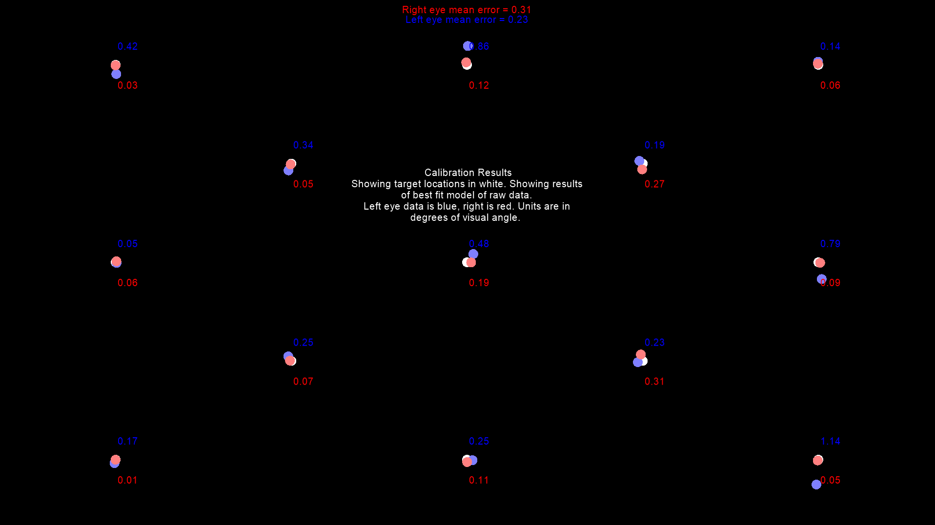
Once all 13 data points are collected, results are presented on the display. Recall that the purpose of this calibration is to build a model of the change in the pupil-corneal reflection vector as we look around the display; the raw collected data is then applied to this model, and the error is shown for each tracked eye, and each target location. The error is shown in degrees of visual angle.
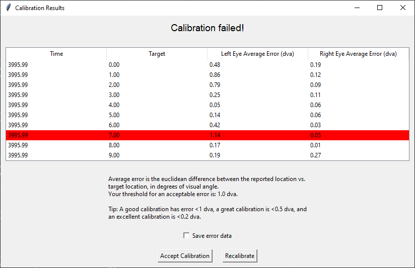
In addition to this visualization, results are presented in a table to the experimenter. Errors greater than the accepted threshold are highlighted in red; if any errors exceed this threshold, or return nan (no data collected), the calibration is deemed a failure. The experimenter may then choose to accept the results anyway or recalibrate. If they choose to recalibrate, the gaze-point calibration will be repeated until a calibration is accepted.
Once the tracker has been calibrated to your satisfaction, it will remain calibrated until the hardware is powered off, or the calibration is cleared (e.g., by a new calibration).
Error data may be saved for later reference, along with the calibration parameters used in the session.
What is a “good” calibration? When to accept, and when to recalibrate
The above example results raise an interesting question. Of 26 collected gaze positions, only one failed by 0.14 degrees of visual angle. Is this truly a “bad” calibration?
There is no hard rule for acceptable vs. unacceptable levels of error. Our general guidelines are:
-
Errors < 1 dva = good
-
Errors < 0.5 dva = great
-
Errors < 0.2 dva = excellent
However, these are merely guidelines. You as the experimenter will have to exercise judgment, particularly in cases like the above calibration where most of the errors are < 0.5 dva (great) and only one data point is not very good.
The threshold you set for acceptable error needs to strike a balance between recalibrating many times to get a better result, the accuracy requirements of your experiment, and the comfort of your participant.
One important factor to consider is the location of the error. Broadly speaking, central errors in calibration are more problematic than errors near the edges. In the above case, the error is target #7, which is in the bottom left corner of the display:
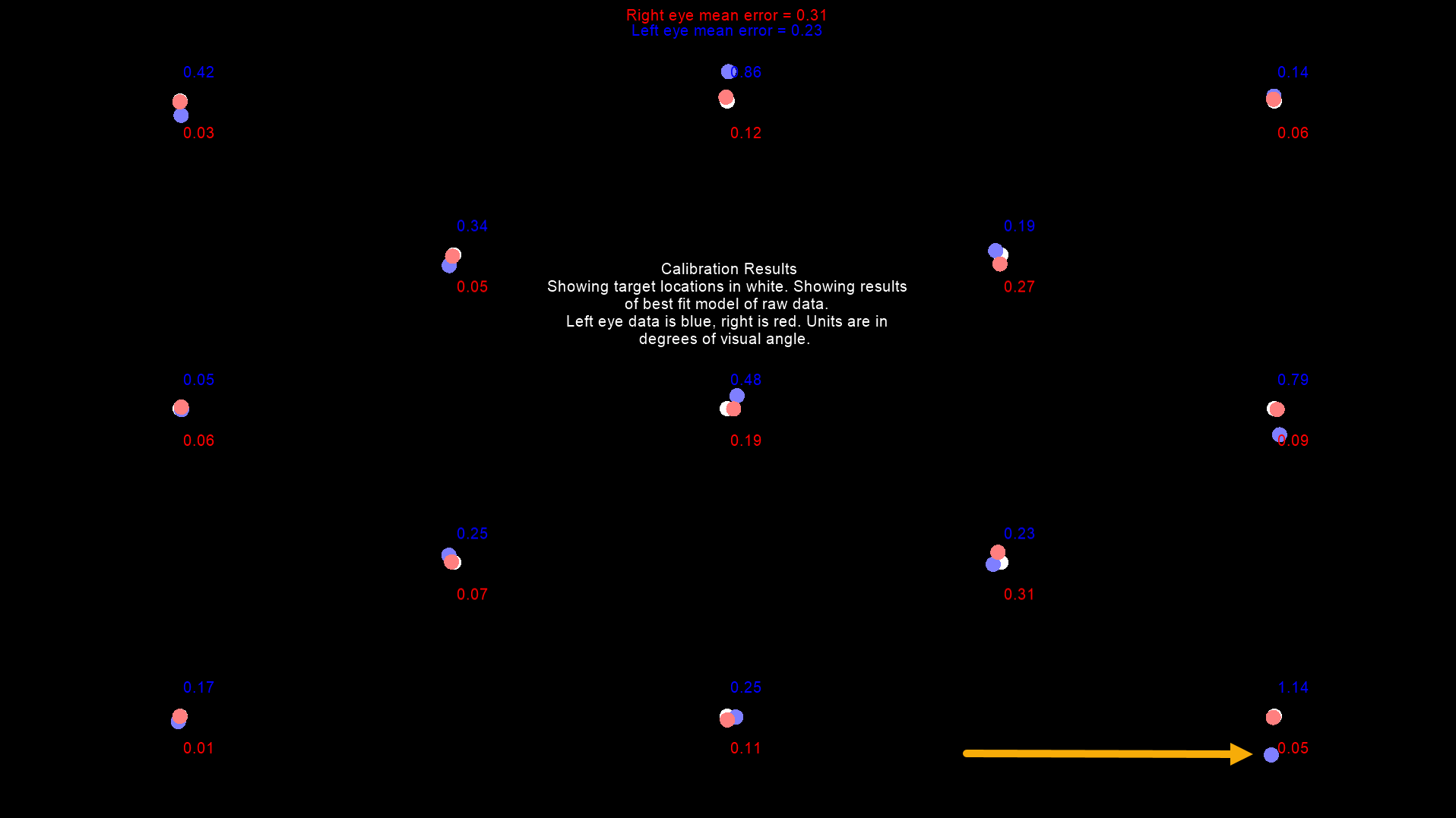
In cases like this, consider how critical this area is to the scope of your study. We recommend scaling the calibration target distribution to the area of the screen your study uses. That said, the very corners of this distribution may still fall outside the boundaries of your stimulus locations.
Ultimately the decision to accept errors above the predefined threshold lies with the experimenter. As you collect more data, analyze pilot results, and become more familiar with the calibration procedure, you will develop an intuition for what is an acceptable level of error in a gaze point calibration for your specific study.
Drift checks and intermittent recalibration in long studies
Calibrations degrade over time. Even the best chinrest will not keep a participant completely still; they may slouch, shift their posture, or speak, all of which can lead to repositioning that degrades the performance of the model. Estimated gaze position thus begins to “drift.” At some point, this drift may begin to exceed your accepted threshold for error.
On the other hand, recalibrating mid-experiment “just in case” is also a potential problem. You may accidentally overwrite a still-decent calibration. Therefore, before committing to a recalibration, we suggest performing a simple “drift check” to see if your current calibration is still valid.
Drift checks present all or a subset of the original targets used for the calibration, collect some gaze data, and determine whether the current error between the estimated and real gaze position now exceeds the original acceptable threshold.
Drift checks ideally are embedded within a study, and do not disrupt the flow of the experiment. Thus, in Python our drift check routine does not present any results on the stimulus display. Instead, they are shown on the experiment display along with a simple prompt to continue or recalibrate:
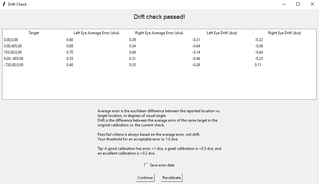
If the check fails, it is probably time to recalibrate. Clicking on the ‘Recalibrate’ button will trigger another gaze point calibration. Otherwise, you can continue with the assurance your tracking is still accurate. You can save errors in Python by checking the ‘save errors’ box in the drift check results.
As the above example illustrates, it is possible to have negative drift. This means that the average absolute error of the current gaze data is less than that of the original calibration. It may be the participant is now used to the protocol and has an easier time fixating targets, or the positional adjustments they have made have improved the accuracy of the model. In any case, negative drift is a good sign your calibration is still accurate enough to continue the study.
Summary
The goal of this VOCAL is to provide a step-by-step walkthrough of the TRACKPixx3 calibration procedure. This procedure should be run at the beginning of each new eye-tracking session. The simple steps are to configure settings, focus the camera, perform a gaze-point calibration and assess the results. The goal of the calibration is to build a model of the systematic change of the vector between the pupil center and corneal reflection as the participant looks around the display. This model can then be used, in real-time, to infer the current location on the screen the participant is looking at.
Now that you are familiar with the principles and the general structure of eye-tracking calibration, it’s time to try it out! The following pages of this VOCAL are simple demonstrations of how a calibration procedure may be embedded in a Python, MATLAB, or LabMaestro experiment. Code and downloadable experiment files are provided.
Appendix I: List of tracker and calibration settings
Below is a comprehensive list of settings for the TRACKPixx3 and calibration routines. Note that there are additional “hidden” settings used by VPixx developers that generally should not be modified by end-users; these are not reported here.
|
Tracker settings |
Description |
Options |
Recommendations |
|---|---|---|---|
|
Console Overlay Mode |
Configuration options for the camera view and display view on the console monitor. |
Full Stimuli Half Tracker
|
Only available in LabMaestro |
|
Distance |
Distance from the TRACKPixx3 lens to the participant’s eyes |
|
Not to be confused with viewing distance, which is the distance between the display and the participant’s eyes |
|
Fixation Detection |
Determines parameters for automatic fixation flags. |
|
Fixation detection is based on a simple rolling window average. Arguments include maximum speed and the minimum duration. The eyes need to move slower than the minimum speed for the minimum duration or longer for the flag to rise. LabMaestro uses degrees of visual angle/second, while APIs use pixels/second. |
|
Gaze Vector Mode/Tracking Mode |
Whether the tracker operates using the pupil-corneal vector or a vector between the camera origin and corneal reflection. |
0 = pupil-CR vector
|
Almost all experiments should use setting 0 (the default). Tracking mode 1 is exclusively for head-fixed NHP research, specifically when mode 0 does not prove stable. |
|
LED intensity |
Intensity of the infrared lamp output |
value from 0-8 |
Leave on the default setting of 8 (maximum) |
|
Lens |
Which camera lens is the TRACKPixx3 currently equipped with |
0 = 25 mm
|
Lens type is printed on the side of the lens itself. This can be saved in the tracker settings using API commands (not available in LabMaestro). Note: This property is purely descriptive, it will not affect tracking behaviour. |
|
Iris size |
An estimate of the diameter of the iris in pixel space. Used to improve tracking algorithm. |
|
Varies from participant to participant. Adjust during step 2 of the calibration. |
|
Saccade Detection |
Determines parameters for automatic saccade flags. |
|
Saccade detection is based on a simple rolling window average. Arguments include minimum speed and the minimum duration. The eyes need to move faster than the minimum speed for the minimum duration or longer for the flag to rise. LabMaestro uses degrees of visual angle/second, while APIs use pixels/second. |
|
Search Limits |
Optional regions defined around the eyes, in camera space, that limit the algorithm’s search area. |
|
Use when glare/other reflections are present in camera image. Adjust during step 2 of the calibration |
|
Species |
Setting optimization for humans or non-human primates |
0 = human
|
Use the species of your participants. The default is 0. |
|
Calibration settings |
Description |
Options |
Recommendations |
|
Acceptable offset |
The threshold for acceptable error in the calibration results. In degrees of visual angle. Any recorded errors beyond this point will trigger a calibration “FAIL” message. The operator can elect to recalibrate or accept the results. |
|
For humans, a good calibration has error <1 dva, a great calibration is <0.5 dva, and an excellent calibration is <0.2 dva. You may need to relax your threshold for participants who have difficulty following instructions or making eye movements (e.g., children, patients). |
|
Automatic vs. Manual |
Automatic calibrations present targets for a specified duration. Manual calibrations require the operator to press a key on the keyboard to continue to the next target. In LabMaestro, manual calibration points can be re-run individually if the calibration for that target is unacceptable. |
Checkbox or dropdown menu, depending on the application |
Defaults to Automatic. Consider manual if you have reason to believe the participant cannot follow instructions well and may need additional time/multiple tries. |
|
Background Colour |
Colour of the background of the calibration routine |
RGB triplet |
Should align with your experiment. E.g., if your experiment uses a grey background, use the same colour in your calibration procedure. |
|
Calibration Mode |
Which eye(s) should be calibrated during tracking |
Left Eye Only
|
The default setting is both eyes. If tracking is consistently bad in one eye (e.g., if there is a shadow over that eye caused by an MRI head coil), consider tracking only the ‘good’ eye. |
|
Number of targets |
The number of targets presented during calibration. Targets follow the pattern below. Using a smaller number of targets than 13 will include a subset of these (starting from 0). .png?cb=a9599b972832f17d3a28a33890ff0dcb)
|
|
13 points is recommended for adult humans. Consider a subset of the original 13 for NHP, infants, or other populations with attentional limitations. |
|
Target colour |
Colour of the calibration target |
RGB triplet |
Use a high-contrast colour that aligns well with your experiment stimuli. |
|
Target display time |
How long each target should appear while calibrating in Automatic mode. |
|
Make sure your participants have time to react and saccade to the target. Afford longer times for naive participants. If your target is an animation, ensure the animation has time to play. |
|
Target image |
User may select an image or animation file to serve as the calibration target. |
|
NHPs and young humans like to look at faces, toys and animated images. If the standard target dots are boring, consider using an image/animation. Currently available only in LabMaestro. |
|
Trigger key |
When in Manual calibration mode, the Trigger key prompts the onset of the next target and thus controls the calibration progression. |
|
Currently available only in LabMaestro. |