The VIEWPixx3 /OLED was designed as the world’s first research-grade OLED display; it has deterministic timing and rapid pixel responses, which are hallmarks of our research-grade LCD monitors (the VIEWPixx/EEG and VIEWPixx/3D), but also includes the desirable qualities inherent in OLED panels: high uniformity of luminance across the screen, wider viewing angles, wider color gamut, and an “infinite” contrast ratio (black is truly black, as OLED pixels actually shut off when displaying black).
As explained in our article Measuring Pixel Behaviour and Temporal Characteristics of the VIEWPixx /3D, LCD monitors update their pixels by changing the molecular structure of liquid crystals in their panels; the pixel response time, or the time for the liquid crystal structure to transition between states, can vary across pixel values, often taking up to several milliseconds. Unfortunately, these characteristics can increase display ghosting and motion blur and, in the case of alternating-frame dichoptic stimuli, add cross-talk between left and right eye images; cross-talk is the imperfect separation of the two eyes' images during dichoptic presentation. Our innovative scanning backlight technology, implemented in our research-grade LCD monitors, minimizes these effects by only illuminating rows of pixels once they have already begun to stabilize. In OLED panels, pixels are composed of self-emissive LED light-sources; therefore, pixel transitions occur very rapidly, well under 1ms (on the order of tens of microseconds). For this reason, our VIEWPixx3 /OLED display has inherently rapid pixel response times which prevent motion blur and ghosting artifacts, and in the case of frame-sequential dichoptic presentation, cross-talk.
As with all of our displays, the VIEWPixx3 /OLED also has deterministic timing. After a new video frame starts being received on the display, and following a very small and fixed temporal delay, the display begins updating its pixels row-by-row. After only ~2ms, the entire display will have updated all of its pixels (from top to bottom), for a given frame. This behavior is consistent, and therefore, fully deterministic. Deterministic timing is important for researchers who want to precisely relate, or correlate, visual events on the monitor with physiological recordings, like EEG, MEG, OPM, single-unit recordings etc. Therefore, having a precise marker or “trigger” synchronized with video refresh is of utmost importance. VPixx displays have a special Pixel Mode feature that detects video frame onset as the signal reaches the display hardware and sends a digital pulse to indicate this moment; for VIEWPixx3 /OLED, this digital pulse is sent the moment that the first row of pixels will start updating on the display. Combined with an understanding of our display technology, we can thus characterize display illumination behaviour with an extremely high degree of precision, and demonstrate the deterministic timing of our displays.
Measuring pixel illumination on the VIEWPixx3 /OLED
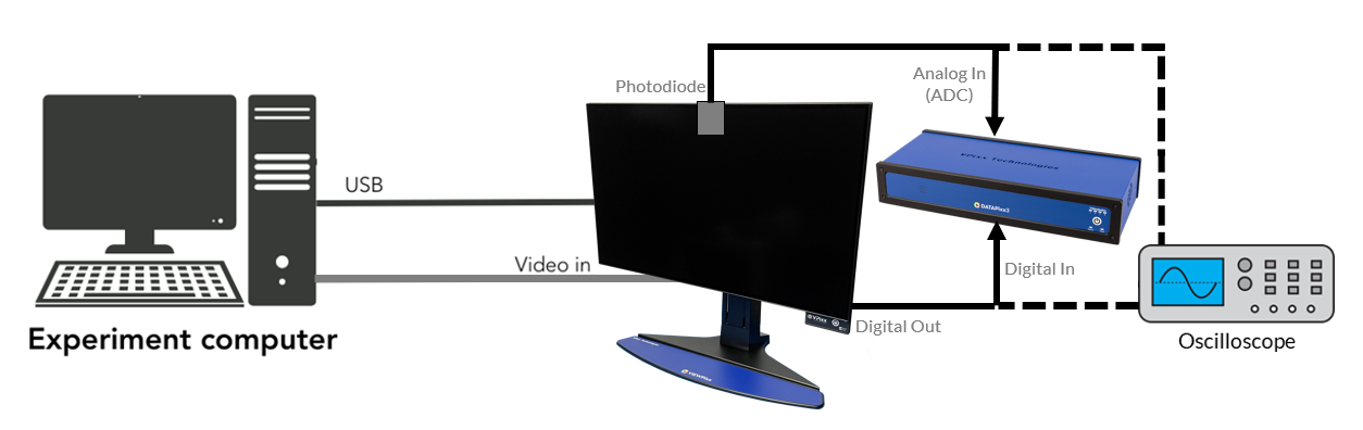
To measure changes in luminance on a display, we use a photodiode, a sensor that converts light into electrical current. In a photodiode, changes in light output result in changes to an output current, and this relationship is highly linear (within the standard operating range of display luminance). When the photodiode is coupled with a trans-impedance amplifier, the change in current is converted to a change in voltage, which is measured on an oscilloscope or an analog data acquisition system (e.g. the analog to digital converters on a DATAPixx3).
To measure luminance changes from a monitor, the photodiode must be placed right up against the screen, and ambient lighting in the room should be kept to a minimum. Here, we will demonstrate how to record the photodiode output using an analog schedule.
The video frame-locked triggers, signaling the start of a video frame, are sent using our Pixel Mode feature. The digital output is read in the digital input port of a DATAPixx3 data acquisition system using a DB25 straight-through cable. We monitor the digital input using a digital input log. Since both analog schedules and digital input logs use the same hardware clock, it is simple to relate the two events with microsecond-precise timing.
The stimulus we display for our photodiode measurements is a simple alternation between white and black frames at 120 Hz. Below is MATLAB/PsychToolBox code for displaying alternating white and black frames while sending Pixel Mode triggers at the start of each frame. The code also shows how to configure and record Pixel Mode triggers and photodiode output, using the DATAPixx3 data acquisition system. The code below can be modified to reflect your own visual stimulus properties.
The code above saves recorded photodiode data in the array adcData and the timestamps of these samples in the adc_time array. The digital input log with our Pixel Modes triggers is stored in the din_data array, and their timestamps are in the d_time array.
Next, we will analyze sample recorded data for measurements on our VIEWPixx3 /OLED display to demonstrate the rapid pixel responses, deterministic timing and how the on-screen location of the measurements affect the time course of luminance changes.
Pixel illumination behaviour of the VIEWPixx3 /OLED
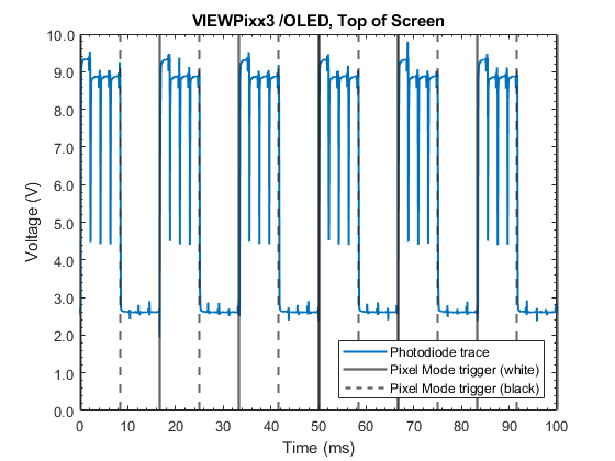
The figure below shows the measured temporal profile of the change in luminance at the top of the screen while the display alternates between white and black frames. Notice the consistency/regularity in the response from frame to frame, demonstrating the fully deterministic timing of the display.
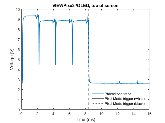
If we zoom in to the first 16ms of the recording (see figure below), we can clearly see that the pixels at the top of the monitor start updating immediately after the first white frame is received, i.e. when the white frame Pixel Mode trigger is sent/received; and the rise of the pixel illumination happens almost instantaneously (<1ms; tens of microseconds). Similarly when the black frame is received by the display (the dotted line corresponding to the black frame Pixel Mode trigger), the drop in luminance also happens instantaneously (<1ms; tens of microseconds). These extremely rapid pixel responses result in smooth frame transitions, with no motion blur or ghosting (and minimal cross-talk for frame sequential dichoptic presentation).
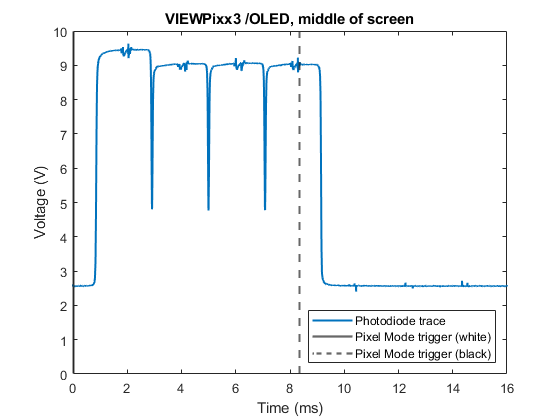
If instead, we place the photodiode at the center of the display, the overall profile of the pixel behaviour is the same, but the luminance ramp onset is later (~1 ms). This is due to the row-by-row updating of pixels, as discussed in the introduction.
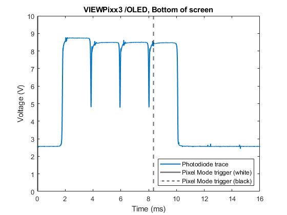
Finally, if we place the photodiode at the bottom of the display, the overall profile of the pixel behaviour is once again the same, but the luminance ramp onset occurs even later (~2ms). Therefore, the entire display refreshes within ~2ms, during the presentation of a frame, much quicker than research-grade LCD monitors.
Summary
The VIEWPixx3 /OLED’s automated triggering, in combination with the DATAPixx3’s analog/digital acquisition system, facilitates measuring the display’s subframe illumination properties.
Specifically, we have demonstrated that the VIEWPixx3 /OLED has:
-
Rapid and symmetrical rise/fall times ensuring minimal motion blur and a clearly defined pixel onset/offset
-
Fully deterministic timing of the pixel transitions, with respect to the frame transmission start, which is precisely synchronized with Pixel Mode triggers.
The rapid pixel responses are an inherent property of OLED displays, as the panel is composed of self-emissive LED light sources with switching times well under 1ms. Since our VIEWPixx3 /OLED does not rely on scanning backlight technology to achieve these rapid pixel responses, the display has overall greater luminance output, compared to our research-grade LCD displays with scanning backlights.
It is important to note that Pixel Mode triggers (or customizable Pixel Sync triggers) ensure digital trigger output is synchronized to frame data transmission start with microsecond precision. On a VIEWPixx series monitor, like our VIEWPixx3 /OLED, image presentation begins immediately upon receipt of frame data. There is no pre-processing or buffering, which means that the reception of a video frame, combined with an understanding of the row-by-row pixel updating, is enough to characterize visual stimulus properties with millisecond precision or better. This directly translates to more precise behavioural and neurophysiological data segmentation, and enhanced reliability in your research. In addition, the resulting improvement in analytical power may achieve significant results with fewer replications, thereby shortening test sessions.