RESPONSEPixx button boxes offer a microsecond-precise method of collecting participant responses in lab and neuroimaging settings. This VOCAL guide explains the logic of button boxes, why we make them, and how to use them in their experiments.
The guide ends with a dedicated troubleshooting section for common issues RESPONSEPixx users can encounter.
Why not use USB?
A USB keyboard or gamepad polls at a fixed rate — typically 125 Hz (8 ms) on most operating systems, though some gaming peripherals achieve 1000 Hz (1 ms). The timestamp of a button press is therefore determined by when the OS polling rate, not when the button was physically pressed.
Polling via the operating system introduces variable latency; in a typical setup, the total system delay between a physical button press and the moment your experiment code logs it can range from 5–30 ms, with unpredictable variance. See our guide Synchronization Strategies for Multimodal Neuroscience for more on USB-based event logging.
On the RESPONSEPixx, button presses are detected as TTL transitions on the digital input of a dedicated FPGA sampling at a fixed rate of 1 MHz. The timestamp is captured at the moment of the electrical transition. The result is microsecond-accurate response-time measurement using the same hardware clock that timestamps your visual stimulus onset and other VPixx peripherals.
This level of timing fidelity matters most when you need to compare response times across conditions, sites, or sessions.
OS-level jitter introduces noise that inflates your variance and reduces statistical power; a dedicated hardware response device removes that noise at the source.
RESPONSEPixx models and their behaviour
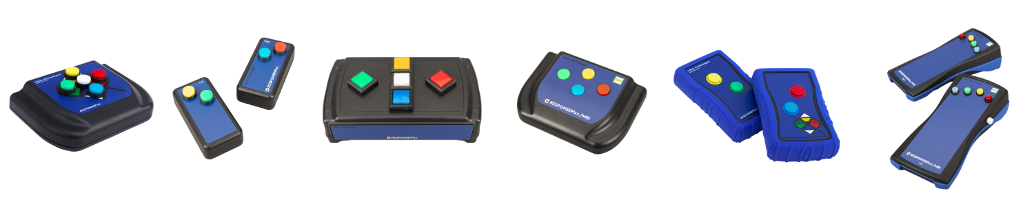
There are six RESPONSEPixx models, divided into two families with opposite polarity conventions.
-
Electrical units have high signal that transitions to low on a press (0->1). They are used in behavioural and EEG labs.
-
MRI/Fiber optic units have a low signal that transitions to high on a press (1->0). They are used in MR-sensitive environments like MRI and MEG.
Why the polarity reversal between types? It has to do with the signal transmission technology. Electrical units use wired connections, and in a wired circuit, pulling a signal low is slightly faster than driving it high. So the electrical units are optimized for the fastest possible edge on the press event.
MRI units use fiber optics. Over a fiber link, there's no speed difference between going high and going low, so that optimization doesn't apply. MRI units use low-to-high because it's simpler to implement and maintain on the fiber receiver side.
In this section, we summarize the six different standard models and their Digital Input mappings.
Electrical units
Electrical units include the RESPONSEPixx Handheld, REPONSEPixx Dual Handheld, and RESPONSEPixx Tabletop. All unit are designed to connect to the DB25 Digital Input port on the VPixx acquisition system (a DATAPixx, PROPixx Controller, or VIEWPixx series monitor).
On electrical RESPONSEPixx units, channels are high by default, represented by a value of 1. A button press pulls the channel low (a value of 0). The idle state reads as all 1s.
RESPONSEPixx Handheld
Digital input mapping:
|
DIN 0 |
DIN 1 |
DIN 2 |
DIN 3 |
DIN 4 |
|
🔴 Red |
🟡 Yellow |
🟢 Green |
🔵 Blue |
⚪ White |
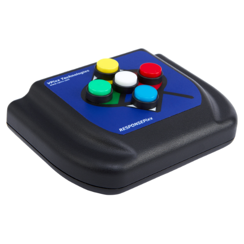
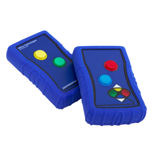
RESPONSEPixx Dual Handheld (2x2)
Digital input mapping:
|
DIN 0 |
DIN 1 |
DIN 2 |
DIN 3 |
|
🔴 Red |
🟡 Yellow |
🟢 Green |
🔵 Blue |
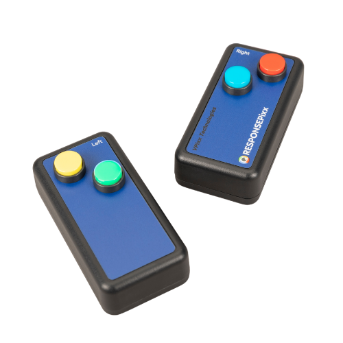
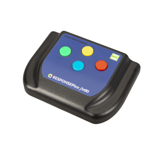
RESPONSEPixx Tabletop
Digital input mapping:
|
DIN 0 |
DIN 1 |
DIN 2 |
DIN 3 |
DIN 4 |
|
🔴 Red |
🟡 Yellow |
🟢 Green |
🔵 Blue |
⚪ White |
LED feedback on electrical units: The electrical RESPONSEPixx models have built-in LEDs behind each button that can be controlled via the digital output. You can illuminate buttons to cue valid responses, provide feedback, or run Simon-says-style games. To use them, set the appropriate digital output pins as outputs using Datapixx('SetDinDataDirection', hex2dec('1F0000')) and then write to the corresponding DOUT channels. See the Simon Game demo for a complete example.
MRI units
Channels are LOW by default. A button press pulls the channel HIGH. This is the opposite polarity to electrical units.
Code written for an electrical unit will not work for an MRI unit without adjusting the logic for how presses are detected. If your code checks for a channel going LOW, it will never see a press on an MRI unit. See the Troubleshooting section for common polarity-related issues.
RESPONSEPixx MRI Handheld
Digital input mapping:
|
DIN 0 |
DIN 1 |
DIN 2 |
DIN 3 |
|
🔴 Red |
🟡 Yellow |
🟢 Green |
🔵 Blue |
RESPONSEPixx MRI Dual 2-Button
Digital input mapping:
|
DIN 0 |
DIN 1 |
DIN 2 |
DIN 3 |
|
🔴 Red |
🟡 Yellow |
🟢 Green |
🔵 Blue |
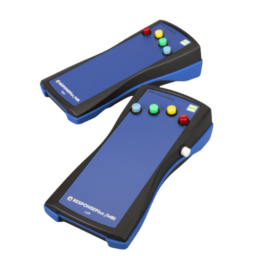
RESPONSEPixx MRI Dual 5-Button (with 10-channel control interface)
Digital input mapping:
Left hand:
|
DIN 0 |
DIN 1 |
DIN 2 |
DIN 3 |
DIN 4 |
|
🔴 Red |
🟡 Yellow |
🟢 Green |
🔵 Blue |
⚪ White |
Right hand:
|
DIN 5 |
DIN 6 |
DIN 7 |
DIN 8 |
DIN 9 |
|
🔴 Red |
🟡 Yellow |
🟢 Green |
🔵 Blue |
⚪ White |
If using a 2-button MRI pad with a 10-input control box, the DIN assignment depends on whether the buttons are plugged into the top row (right-hand channels 5–9) or bottom row (left-hand channels 0–4). The older control box model does not label the rows. Always verify your mapping using the LabMaestro Digital I/O Tester or a diagnostic script.
Custom button boxes
VPixx also manufactures custom button box layouts and button colours. If you have a custom RESPONSEPixx, the DIN channel assignments may differ from the standard mappings listed above. Refer to the documentation provided at time of sale for your specific configuration.
Two methods for reading button activity in code
There are two approaches to reading digital input from a RESPONSEPixx. Which one you choose depends on your experiment design.
Method 1: Digital Input Log (DIN log)
The DIN log is a hardware-based recording schedule that captures every transition on the digital input port at 1 MHz sampling.
Each log entry records the full DIN state and a microsecond-accurate timestamp on the VPixx hardware clock.
When to use: Most experiments. The DIN log captures all events with hardware-timed precision. You start the log, run your trial, and read back all events after the trial ends (or check periodically).
Advantages: microsecond timing, captures all events including rapid presses and releases, timestamps are on the hardware clock.
Disadvantages: requires setup and shutdown; log must be read and parsed.
Compute press duration from the DIN log: The DIN log records both the press (rising or falling edge, depending on unit type) and the release (opposite edge). By subtracting the timestamp of the press event from the timestamp of the corresponding release event, you can compute the exact duration the button was held. This is useful for paradigms that require sustained presses, release-based responses, or press-and-hold interactions. Each button press generates two log entries — one for the press transition and one for the release.
Release-based response times are faster: For many motor tasks, participants respond faster when the response is a button release rather than a button press. Tapping a pre-held button eliminates the ballistic component of the press movement and isolates the decision-to-action interval. If your paradigm can accommodate it, consider having participants hold a button and release on target onset. The DIN log captures both edges, so you can compute release-based RTs directly. Further reading: Milliken, B., & Lupiáñez, J. (1999). Inhibition of return is asymmetrically obtained by press and release responses. Reported release RTs ~20–30 ms faster than press RTs. See also: Ulrich, R., & Mattes, S. (1996). Does immediate arousal enhance response force in simple reaction time? Quarterly Journal of Experimental Psychology, 49A(4), 972–990.
Method 2: Polling DIN value (GetDinValues / RegWrRd)
You can read the instantaneous state of all digital input channels at any time by updating the register cache and reading the current DIN value.
When to use: Simple go/no-go checks (e.g., "is the button currently pressed?"), waiting for a specific state before proceeding (e.g., waiting for an MRI trigger), or when you only need to know the current state and don't need a precise timestamp of when the transition occurred.
Advantages: simple, no log setup required.
Disadvantages: timing is limited to your USB polling rate (typically monitor refresh or a software wait loop), and is therefore less precise than the log. Depending on your polling rate, you can also miss rapid events that occur between polls.
Debounce
Mechanical buttons produce electrical noise ("bounce") when pressed or released — the contact may rapidly make and break several times over a few milliseconds before settling. Without debounce, this can register as multiple presses in the DIN log.
VPixx data acquisition hardware has a built-in debounce filter that can be enabled in software. When enabled, the hardware ignores transitions that occur within a short window after the initial transition.
MATLAB:
Datapixx('EnableDinDebounce');
Datapixx('RegWrRd');
Python (libdpx):
dp.DPxEnableDinDebounce()
dp.DPxWriteRegCache()
Always enable debounce when using RESPONSEPixx button boxes. It eliminates phantom events with no meaningful impact on timing precision.
Button forwarding to third-party receivers
In neuroimaging environments (EEG, MEG, fMRI), you often need to send button-press events to a third-party recording system in addition to logging them in your experiment code.
Our family of data acquisition controllers (VIEWPixx /3D, VIEWPixx, PROPixx Controller, DATAPixx hubs) support automated button forwarding: the hardware listens for digital input transitions and uses these to trigger digital outputs. This removes the PC from the signalling loop, eliminating OS and USB timing jitter.
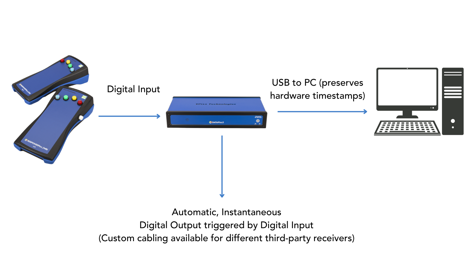
Once set up, forwarding runs autonomously until it is disabled. Your experiment PC can access the button activity via the methods described above, while the third-party receiver logs whatever digital output you’ve configured to send automatically. The mapping is configurable, so you can stack multiple buttons onto fewer channels (e.g., 1 pulse for red, 2 pulses for blue) or use 1-1 channel mapping for easily interpretable output.
Key features:
-
Map any DIN channel to any DOUT channel
-
Configure custom pulse durations and waveforms per button
-
Combine with Pixel Mode triggers (e.g., Pixel Mode B on DOUT 16–23 while button forwarding uses DOUT 0–9)
-
Supports press-only, release-only, or press-and-release forwarding
See: Forwarding RESPONSEPixx Button Activity to a Third-Party Receiver
Interpreting Digital Inputs
What do Digital Input signatures look like?
Every digital input channel on the VPixx hardware is one bit in a binary number. When you read a DIN value, either from the DIN log or from GetDinValues, you get back a single decimal number that encodes the state of all channels simultaneously.
Think of it like a row of light switches. Each switch is one DIN channel:
-
On electrical units, a switch that is "on" is a 0; a switch that is "off" is a 0. Idle unconnected channels are at 1.
-
On MRI units, a switch that is "on" is a 1; a switch that is "off" is a 0. Idle unconnected channels are at 1.
Line up all the switches in a row and you get a binary number. The DIN log reports that binary number converted to decimal.
|
Binary |
Decimal |
|---|---|
|
0000 0001 0000 |
(24) = 16 |
The key point is this: a button press changes one bit, which changes the decimal number. To figure out which button was pressed, you need to figure out which bit changed.
Below is an interactive explorer that provides three examples of DIN states:
-
For an electrical 5-button unit
-
For an MRI 4-button unit
-
For an MRI 10-button unit with an MR trigger input on DIN 15 (idling low, high on trigger)
Try toggling a few channels on and off to see what happens to the binary and decimal digital input states.
Practice: Interpreting an example digital input log
Ready to try interpreting digital input codes? Here’s a couple of example log outputs. Our APIs return the codes in decimal; the binary is provided beside this for intepretation. See if you can determine what was happening in the log at each time point.
For an electrical handheld unit:
|
TimeTag |
DIN code logged |
Binary equivalent |
Event |
|---|---|---|---|
|
184.859 |
65519 |
1111 1111 1110 1111 |
|
|
185.882 |
65535 |
1111 1111 1111 1111 |
|
|
186.705 |
65533 |
1111 1111 1111 1101 |
|
|
187.005 |
65535 |
1111 1111 1111 1111 |
|
For an MRI 10-button unit
|
TimeTag |
DIN code logged |
Binary equivalent |
Event |
|---|---|---|---|
|
1315.334 |
64576 |
1111110001000000 |
|
|
1316.104 |
64608 |
1111110001100000 |
|
|
1316.950 |
64576 |
1111110001000000 |
|
|
1317.344 |
64512 |
1111110000000000 |
|
How to check the state of a specific DIN channel
Instead of comparing against hardcoded decimal values, you can use bitwise operations to isolate and check individual channels. This approach works regardless of what else is connected to the port.
MATLAB:
isPressed = bitand(dinValue, 2^dinNumber);
Python:
is_pressed = din_value & (1 << din_number)
If the result is nonzero, that DIN channel's state is 1. For electrical units, a nonzero result on a button channel means the button is not pressed (channel is HIGH = idle). For MRI units, nonzero means the button is pressed (channel is HIGH = active). Make sure you know which convention your unit uses.
Masking: checking only the specific channels you care about
A mask is a second code that instructs your bit operations to ignore all but the target channels. This makes your code portable across setups, as it doesn't matter what else is connected to the other 20+ channels.
How to build a mask: Add the bit values of your button channels.
For example, you have a 10-button MRI unit and only want to check the right-hand red (DIN 5) and blue (DIN 8):
-
Build the mask:
mask = 2^5 + 2^8→ mask = 288 -
In binary, 288 =
100100000— only bits 5 and 8 are set -
Apply it:
pressedCode = bitand(dinValue, mask)
Now pressedCode can only be one of four values:
|
pressedCode |
Meaning |
|---|---|
|
0 |
Neither button pressed |
|
32 (= 2^5) |
Red pressed |
|
256 (= 2^8) |
Blue pressed |
|
288 (= 2^5 + 2^8) |
Both pressed simultaneously |
It doesn't matter what's happening on the other channels as the mask filters them out.
Button activity in LabMaestro
LabMaestro logs button activity with the same DIN code mechanism as the APIs. However, this code only appears in the trial output. In the timeline, convenience wrappers are used.
For instance, in the WaitForInput command the user simply selects the button box type they are using (electrical or MRI), whether they want to listen for presses or releases, and which buttons are valid responses:
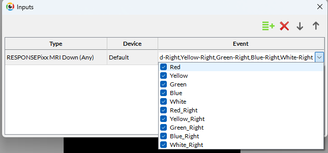
The DIN log codes corresponding to the button activity are saved in the results. For example, here are the outputs of a simple reaction time experiment where a dot position updates on any RESPONSEPixx /MRI 10-button press:
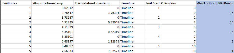
From this output, we can see that on trials 1-3, the 4th bit (24, or 0000 0000 0001 0000) was sent high. On a RESPONSEPixx MRI 10-button, this corresponds to a left-hand white button press.
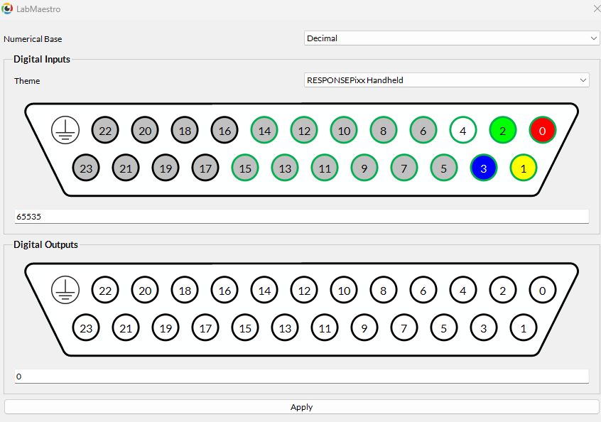
On trial 4, bit 1 changed instead (21, 0000 0000 0000 0010, left yellow press) and on trial 5, bit 0 changed (20, 0000 0000 0000 0001, left red press). When in doubt, you can always use the LabMaestro I/O tester to verify your pin mappings and DIN codes. Right-click on your VPixx control hardware in the Environment, select Digital I/O Tester, and then set the output to Decimal + the RESPONSEPixx unit you have:
Code examples index
Several API and high level references for RESPONSEPixx use exist across our documentation site. They are recorded here for your reference.
MATLAB
|
Example |
Description |
Link |
|---|---|---|
|
Record Response Times (VOCAL video) |
Full video walkthrough: RPx construction, basic interactions, DIN log, reaction time |
|
|
Simple Reaction Time Task |
Flash target, record press on DIN log, compute RT relative to stimulus onset |
|
|
Simon Game |
Audio-visual RT game with debounce, button LEDs (DOUT), and DIN log |
|
|
DOUT Button Schedules |
Automated digital output waveforms triggered by button press/release |
|
|
Button Activity with I/O Hub (TRACKPixx /mini) |
Joystick-style button reading via HebiJoystick toolbox |
Python
|
Example |
Description |
Link |
|---|---|---|
|
Read Button Presses (pypixxlib) |
DIN log with button code dictionary, event loop, timestamp extraction |
|
|
Simple Reaction Time Task (libdpx) |
libdpx wrapper, DIN log, debounce, RT measurement |
|
|
Using VPixx Hardware with PsychoPy (VOCAL) |
ButtonListener class, Builder integration, button checking patterns |
|
|
Digital Output Triggers and Pulse Trains |
Custom DOUT schedules from Python, configurable per-channel |
VOCAL guides (cross-language)
Tools
|
Tool |
Description |
Link |
|---|---|---|
|
LabMaestro Digital I/O Tester |
Real-time visual display of DIN/DOUT channel states; verify button mapping without code |
Built into LabMaestro (right-click device → Digital I/O Tester) |
|
LabMaestro Hardware Simulator |
Simulate RPx button presses without hardware for offline development |
Troubleshooting
Some common issues that RESPONSEPixx users have, and the fixes.
|
Issue |
Likely Cause |
Fix |
|---|---|---|
|
"My button presses aren't being detected" |
Wrong DIN channel assumption. This is the single most common RPx support issue. Users copy code from a colleague, a demo, or a previous project and assume the DIN channels are the same. They are not necessarily the same — it depends on the button box model, which row of the control box the buttons are plugged into, and whether other devices (like an MRI trigger) are also connected. |
Open the LabMaestro Digital I/O Tester (right-click your device → Digital I/O Tester) and press each button. Watch which channel changes state. Write down the mapping. Use those channels in your code. |
|
"My code hangs waiting for button input" |
Polarity mismatch between code and hardware. This happens when code written for an electrical unit (expects HIGH→LOW) is run with an MRI unit (sends LOW→HIGH), or vice versa. The code waits for a transition that will never occur. Classic example: |
Verify your unit type (electrical vs. MRI) and adjust your press-detection logic accordingly. |
|
"I'm getting double-presses / phantom events" |
Debounce not enabled. Mechanical buttons bounce. Without debounce, a single press can register as 2–5 transitions in the DIN log |
Enable debounce, e.g.,
|
|
“My button codes don't match the documentation” |
Other devices connected to the digital input are changing the idle state.
|
Use bitwise AND with a mask that covers only your button channels. For example, for buttons on DIN 0–3: |
|
“Buttons are physically sticking or jamming” |
Known hardware issue.
|
Try rotating the button in its housing to see if it loosens up.
|