Overview
This page aims to list all Command components and document their properties.
After reading this page, you should:
-
Be familiar with all Command components available in the LabMaestro Experiment Builder.
-
Understand common Command component properties.
-
Understand how you can use Command Properties to alter components.
Commands
Below is a list of all Command components available in the LabMaestro Experiment Builder as of Version 1.12.
Show/Hide Region Commands

In an experimental trial, you may want to place a Region on the testing display for a specific interval, then remove it, perhaps replacing it with another Region.
Hide Region
Hide a named region and its Patterns.
Properties
-
Region: Specify which region to hide. You can select from all regions included in the current Epoch.
Show Region
Show a previously hidden region and its patterns.
Properties
-
Region: Specify which region to reveal. You can select from all regions included in the current Epoch.
Flow Commands
Wait
Pauses the timeline before executing the next command. Often used as the last command in an Epoch to specify how long visual stimuli will stay on the screen.
Properties
-
Enforce Frame Swap: This option forces a frame swap before the wait time begins.
-
Wait Duration: Specifies the duration of the pause in seconds.
-
Random Additional Delay: Maximum additional pause to Wait Duration. If enabled, a random delay between 0 and the defined value is added to the wait time, sampled from a uniform distribution. Disabled by default.
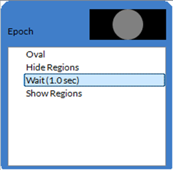
In the above Epoch, the Oval region would be hidden for 1 second before being displayed.
Go To
The Go To command lets you jump from one point in a timeline to another.
Properties
Use the Pointer property to specify the target point in the timeline.
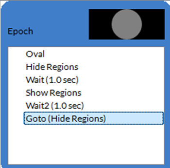
In the above Epoch, the Oval region would be hidden for 1 second before being displayed. Once the GoTo command is reached, the Epoch loops back to the Hide Regions command. Note that, in this case, this produces an infinite loop that will not progress further in the experiment.
Reset Timer
Resets the Time variable to 0.
By default, the Time variable corresponds to the time from the beginning of a timeline. However, you may want to measure time relative to some other reference point within the trial. In such situations, you can include the "Reset Timer" command in the timeline to set the Time value to 0.
The Reset Timer command has no properties.
Abort
The Abort command ends the experiment. It will skip any remaining trials, timelines or components.
Properties
-
Condition: Boolean expression checked to know if the experiment should end. If the expression returns True, the experiment ends.
Set Variables
Used to change the value of a variable during an experiment, such as to change a region or pattern property over time.
Properties
-
Variables: Specify which variables to redefine as well as their new values.
Schedule Commands
The schedule commands allow you to start analog or digital data recordings. For each data type, a separate command handles the start and end of the recording.
Start Analog Recording
Start recording analog inputs (ADC) on the specified channel and at the specified rate. You can also specify a duration to record for only a specific amount of time.
Properties
-
Device: The VPixx device to record analog inputs from.
-
Frequency: How often the schedule records data, in Hz. This value is between 0 and 200,000 Hz.
-
Delay: How long (in seconds) before the schedule starts recording. The maximum delay is 4.29 seconds.
-
Duration: How long (in seconds) to record data for.
-
Channels: The channels from which to record data. Channels correspond to the device's respective ADCs. For example, Channel00 is ADC0.
Stop Analog Recording
Stops recording analog input (ADC) on a specific device and saves the data to a file.
Properties
-
Device: The VPixx device to record analog inputs from.
-
File Name: The name of the file to save the analog recorded data to.
Analog Out Signal
This command was added in Version 1.12.0.
Starts an analog output schedule.
Properties
-
Device: The VPixx device to record analog inputs from.
-
Sampling Rate: Define the sampling rate of the analog signal being output.
-
DACs: Define the parameters of the analog signal sent from each DACs (0, 1, 2, 3).
-
Repetitions: Define how many times the analog output schedule will repeat.
Start Digital Recording
Starts recording digital inputs (DIN) on a specific device.
Properties
-
Device: The VPixx device to record the digital inputs from.
Stop Digital Recording
Stops recording digital inputs (DIN) on a specific device and saves them to a file
Properties
-
Device: The VPixx device to record the digital inputs from.
-
File Name: The name of the file to save the digital input recorded data to.
Measure I1 Luminance Color
This command was added in Version 1.12.0.
Uses a connected I1 Device to measure the screen luminance.
Properties
-
Integration Time: Sets the maximum time taken for a given measurement in seconds.
Input Commands
LabMaestro Experiment Builder offers two ways to monitor inputs: one that blocks (WaitForInput) and one that registers events without blocking (ListenForInputs).
These commands support:
-
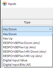
Keyboard via Key Down and Key Up. Key Down corresponds to when a key is pressed down, and Key Up to when a key is released.
-
Digital inputs monitored from a VPixx device. You can access these in multiple ways: Digital Input Value, Digital In Bits, RESPONSEPixx Down, RESPONSEPixx Up, RESPONSEPixx MRI Down, and RESPONSEPixx MRI Up.
For Digital In Values, the values of the first 16 digital inputs must match the event provided.
In the case of Digital In Bits, you select all the bits to be triggered simultaneously. For this condition to pass, all the selected bits must have transitioned.
For RESPONSEPixx Down or RESPONSEPixx MRI Down, any of the selected buttons must be pressed. If the selected event has two buttons, pressing either will cause the condition to pass.
In the case of RESPONSEPixx Up or RESPONSEPixx MRI Up, any of the selected buttons must be released. For instance, if the event you choose has two buttons, releasing any one will cause the condition to pass.
Listen for Inputs
Non-blocking command that instructs LabMaestro to monitor inputs during the experiment. Supports keyboard inputs, as well as the following standard RESPONSEPixx and their buttons:
Microsecond-precision response boxes
A response box must be connected to a supported video I/O hub.
RESPONSEPixx: Reliable, ergonomic response boxes for use in behavioural research laboratories. Standard models support input from 4 or 5 buttons.
|
Supported button |
|||
|
Red |
✅ |
✅ |
✅ |
|
Yellow |
✅ |
✅ |
✅ |
|
Green |
✅ |
✅ |
✅ |
|
Blue |
✅ |
✅ |
✅ |
|
White |
✅ |
- |
✅ |
|
Red_Right |
- |
- |
- |
|
Yellow_Right |
- |
- |
- |
|
Green_Right |
- |
- |
- |
|
Blue_Right |
- |
- |
- |
|
White_Right |
- |
- |
- |
RESPONSEPixx MRI: Fibre-optic versions of our RESPONSEPixx button boxes for MRI, MEGs, OPMs, etc. Standard models support 4 or 10 buttons.
|
Supported button |
|||
|
Red |
✅ |
✅ |
✅ |
|
Yellow |
✅ |
✅ |
✅ |
|
Green |
✅ |
✅ |
✅ |
|
Blue |
✅ |
✅ |
✅ |
|
White |
- |
- |
✅ |
|
Red_R |
- |
- |
✅ |
|
Yellow_R |
- |
- |
✅ |
|
Green_R |
- |
- |
✅ |
|
Blue_R |
- |
- |
✅ |
|
White_R |
- |
- |
✅ |
Properties
-
Log Event: Toggle to record the properties of the input in the data file. The log includes the key pressed, the time of the key press, and the time of the key release.
-
Save to Variable: Save the input properties to a variable defined earlier in the experiment.
-
Inputs: Define which keys the command should listen for. An input not defined in this property is ignored. If no keys are defined, all inputs are recorded.
Wait for Inputs
Instructs LabMaestro to monitor inputs during the experiment, stopping the experiment flow until either an input is recorded or the delay defined in the timeout property is reached. It supports the same hardware as ListenForInputs.
Properties
-
Enforce Frame Swap: This option forces a frame swap right before the wait command starts.
-
Redefines Expected Inputs: Toggle to redefine monitored inputs. This property is relevant if multiple commands listen for inputs throughout an epoch. If it is turned off, previous inputs continue to be monitored.
-
Time Held: Define the duration the input must be held to be counted as valid.
-
Timeout: Define the amount of time the software should wait for the defined input. After this time has passed, the experiment timeline will progress regardless of whether an input was recorded.
-
Inputs: Define which keys the command should listen for. Any recorded input of a key not listed is ignored. If no keys are defined, all inputs are recorded.
-
Last Event: This read-only field shows what information can be accessed by a future expression from this WaitForInputs command.
-
Log Event: Toggle to record the properties of the input in the data file. The log includes the key pressed, the time of the key press, and the time of the key release.
-
Save to Variable: Define the variable to which input data is saved.
Wait for Text
This command was added in Version 1.11.0.
Waits for the participant to enter text on their keyboard, then stores it in a variable.
Properties
-
Enforce Frame Swap: This option forces a frame swap right before the wait command starts.
-
Save to Variable: Define the variable to which to save the text input.
-
Timeout: Set a maximum amount of time (in seconds) that the command will wait before proceeding to the next step in the experiment.
Wait for Gaze
This command was added in Version 1.12.0.
Waits until the participant’s gaze position is recorded within a specific region.
Properties
-
Enforce Frame Swap: This option forces a frame swap right before the wait command starts.
-
Region: Select the target region of interest (ROI) where the gaze should be measured. Fixations outside the ROI will not be recorded by this component.
-
Timeout: Set a maximum amount of time (in seconds) that the command will wait before proceeding to the next step in the experiment.
-
Time Held: Specify the amount of time during which the participant’s gaze must remain within the ROI for the component to register it as an input.
-
Region Scale: The proportion of the region where the participant’s gaze is considered as an input.
Wait for Mouse
This command was added in Version 1.12.0.
Waits until a given mouse action occurs on a defined region of interest.
Properties
-
Enforce Frame Swap: This option forces a frame swap right before the wait command starts.
-
Region: Select the target region of interest (ROI) where the mouse input should occur. Fixations outside the ROI will not be recorded by this component.
-
Timeout: Set a maximum amount of time (in seconds) that the command will wait before proceeding to the next step in the experiment.
-
Time Held: Specify the amount of time during which the participant’s mouse must remain within the ROI for the component to register it as an input.
-
Region Scale: The proportion of the region where the participant’s mouse is considered as an input.
-
Action: Define the type of mouse action that will be considered an input:
-
Hover: Hovering the mouse cursor over the ROI is registered as an input.
-
Left Click: Left-clicks while the mouse cursor is over the ROI are considered an input.
-
Right Click: Right-clicks while the mouse cursor is over the ROI are considered an input.
-
Middle Click: Middle-clicks while the mouse cursor is over the ROI are considered an input.
-
Audio Commands
Play Sound
Play a pre-recorded sound in your experiment. Cognitive experiments often require the presentation of auditory stimuli, such as recorded speech. Any output device can be selected, including VPixx devices.
Properties
-
Device: Specify playback device.
-
Sound Type: Specify the type of sound played.
-
If Media: Use the Resource property to specify which audio file to play.
-
If Tone: Use the Tone property to set the audio playback parameters. You may define Amplitude, DC Offset, Symmetry, Frequency, and Shape.
-
From Version 1.12 onwards, you can also specify an Envelope (and the Envelope Width). Options for envelopes are Hann, Cubic and Quadric.
-
-
-
Volume: Adjust the audio playback volume on a scale of 0 to 100.
-
Repeat: Toggle On to play the sound again after it finishes.
-
Duration: Specify the length of the audio playback in seconds.
The Repeat and Duration properties interact differently depending on their values. Here is a table summarizing these interactions:
|
Duration Value |
Repeat Value |
Behaviour |
|---|---|---|
|
0 |
🔳 |
Play once, full duration |
|
Time |
🔳 |
Play for the duration of time |
|
0 |
✅ |
Play until stop command, audio is looped |
|
Time |
✅ |
play for the duration of time, looped |
Pause Sound
Optionally used after a Play Sound command to pause the audio.
Properties
-
All: Toggle to pause all sounds.
-
Sound: If All is off, specify which sound component to pause.
Resume Sound
Optionally, this command can resume audio playback after a Pause Sound command.
Properties
-
All: Toggle to resume all sounds.
-
Sound: If All is off, specify which sound component to resume.
Eye Tracker Commands
Calibrate Tracker
Calibration routine for the eye tracker (TRACKPixx3 and TRACKPixx /mini). Multiple calibration properties can be customized using this command. The Calibrate Tracker command displays visual targets at predetermined screen coordinates and samples eye tracker data accordingly. Eye-tracking calibration is essential for collecting and reporting data in calibrated screen pixel space.
Properties
-
Mode: The calibration procedure used to display calibration targets and collect gaze samples
-
Automatic: During an automatic calibration, a calibration target is presented for the duration specified by Target Stabilization Time, after which gaze samples are automatically collected.
-
Triggered: Tracker sampling begins only when the participant explicitly confirms that they are fixating on the target by pressing the Trigger Key.
-
Manual: This advanced mode requires two displays and active experimenter control. It allows users to accept, reject, and retry different points while accessing calibration results.
-
-
Target Count: Indicates the number of calibration targets used in the calibration process.
The calibration allows up to 25 target locations to use to calibrate the eye tracker. All calibrations are run using various subsets of these 25 calibration targets. The standard calibration grid for a 16:9 aspect-ratio display is a 13-point grid.
A subset of size n contains the first n calibration targets defined in :
|
2 |
14 |
6 |
16 |
4 |
|
18 |
10 |
22 |
12 |
20 |
|
8 |
24 |
1 |
25 |
9 |
|
21 |
13 |
23 |
11 |
19 |
|
5 |
17 |
7 |
15 |
3 |
-
Acceptable Offset (DVA): The threshold for calibration target offset, expressed in degrees of visual angle (DVA).
-
Vertical Coverage: Specifies the proportion of the screen height to include in the calibration as a ratio of the total screen height. The default setting is 80 percent.
-
Horizontal Coverage: Specifies the proportion of the screen width to include in the calibration as a ratio of the total screen width. The default setting is 80 percent.
-
Background Colour: Specifies the calibration screen background colour.
-
Foreground Colour A: Specifies the first colour of the calibration target. Colour A is the colour of the outer ring.
-
Foreground Colour B: Specifies the second colour of the calibration target. Colour B is the colour of the inner ring.
-
Target Stabilization Time: Specify the number of milliseconds before collecting each target's gaze samples. If the target properties include size or colour changes, the targets are animated during this time.
-
Target Min Size: The minimum radius of each calibration target in pixels.
-
Target Max Size: The maximum radius of each calibration target, in pixels.
-
Custom Target: Selects an image or video media from your project's Resources to use as a calibration target. This property is optional.
-
Media Scaling: Magnification factor used to resize the media used as a custom target.
-
Trigger Key: When calibration mode is set to "“triggered"”, this specifies the keyboard key that initiates gaze sampling for the current calibration target.
-
Failure Prompt: When turned on, a prompt with information will appear if a calibration fails to complete.
-
Precalibration Countdown: This displays a specified value countdown before the calibration procedure begins. No countdown appears if the pre-calibration countdown is 0.
-
State: A read-only property describing the state of the calibration:
-
Pending: The Calibrate Tracker component has not run yet.
-
Ongoing: The calibration procedure defined by the Calibrate Tracker component is currently being executed.
-
Succeeded: The previous calibration procedure attempt, defined by the Calibrate Tracker component, was completed successfully.
-
Failed. The previous calibration procedure attempt, defined by the Calibrate Tracker, either failed or was aborted.
-
-
Calibrated: Read-only property reporting whether the calibration was successful.
-
Average Offset: The average offset between the gaze location and the target dot, calculated on the eyes identified in Eye Selection on the Setup TRACKPixx3 screen.
Validate Tracker Calibration
Validation routine to run after the tracker calibration.
This component has the same properties as the calibration component.
Start Tracker Recording
Initiates a TRACKPixx recording schedule. With a TRACKPixx3, this initiates a 2KHz binocular TRACKPixx3 recording schedule using the DATAPixx3's microsecond-precision clock and integrated video I/O subsystem. With a TRACKPixx/mini, this initiates a 120 Hz binocular recording.
This component has no editable properties.
Stop Tracker Recording
Always used after a Start Recording Tracker command to stop the recording schedule. This command saves the schedule in the Recordings section of the Project Panel.
You can open Recordings using LabMaestro's Recordings and Built-In Data Visualization.
Properties
File Name: Name of the output fixation data.
Output Commands
There are multiple ways to send signals from VPixx devices. If you are used to Pixel Mode, this command is available in LabMaestro. If you are used to sending triggers using digital output schedules, this is possible using the DATAPixx trigger output.
Pixel Mode
The pixel mode command allows you to send a specific trigger using only the top left pixel's colour value. This command automatically enables the right mode on the selected device to send the trigger for the requested duration.
Properties
-
Device: The device that will send the digital output trigger.
-
Pixel Mode: The chosen mode, which can be RGB (controls all 24 digital outputs), GB (controls the lower 16 digital outputs), B (DATAPixx3 Only, controls the lowest 8 digital outputs)
-
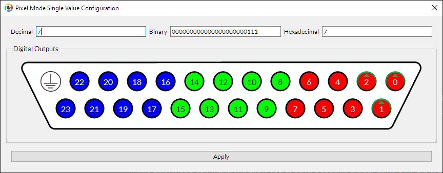
Value Mode: The mode to use to provide the trigger value. It can be an expression that depends on other variables, a single value, or multiple values (an RGB triplet).
If you pick a single value, you can set it directly using the graphical tool that displays the digital output on your device.
-
Duration Mode: Specifies how long you want the trigger to last. This duration can be defined in video frames or seconds, or the trigger can continue until there is another pixel mode trigger or the experiment is completed.
-
Frames/Seconds: Time for the trigger in the respective unit.
DATAPixx trigger output
Configure the characteristics of a digital trigger signal generated from a VPixx video I/O hub. Once the instructions are received, the device sends the digital trigger command via USB and executes it.
Properties
-
Mode: Selects which types of trigger to send:
-
"PositivePulse": A single square wave pulse voltage change from 0V to 5V, returning to 0V.
-
"NegativePulse": A single square wave pulse voltage change from 5V to 0V, returning to 5V.
-
-
Digital Output: The digital output value you want to trigger. Please note that this is not the pin number; you can find the mapping of a pin to the digital output in the user manual of your hardware.
-
Duration: Defines the duration of each pulse in milliseconds. In other words, how long does it stay at 0V or 5V before returning to its initial state?
-
Duty Cycle: Ratio of time the signal stays in the positive or negative state.
-
Repetitions: Specifies how many times to repeat the trigger pulse.
System Commands
Capture Screen
This command captures an image of your screen at a given moment and saves it as a picture file. The captured screen is saved as a JPG in the Recordings section of the Project Panel. The capture screen command helps generate images for publications and presentations.
Properties
-
File Name: The name of the output JPG file.
-
Frame (V. 1.11.0): Specifies which eye the picture is taken from if you are using a 3D display mode. You can choose either the left or right eye, or the combined image from both eyes.
As of Version 1.11.0, the Capture Screen command now supports 3D and high-refresh-rate display modes.
Log
This command allows you to record a text string or a number in the logs file. You can use this component to save information from variables or to support your post-experiment analysis.
Properties
-
Log Type: Number or text, depending on what you wish to store.
-
Value: The value to be logged.
System Command
This command runs a system command (e.g., a terminal command). It can be useful for specific calculations, evaluations, or features not directly implemented in LabMaestro. You can save the command's return value output directly to a variable for later use.
Properties
-
Command: The string of the command you want to run.
-
Blocking: Flag, which determines if the timeline should wait or not on the command to finish execution before continuing to the next instruction.
-
Save To Variable: The name of the variable to save the output to.
Related Links