Overview
This page covers the VPixx Devices currently compatible with the LabMaestro Hardware Simulator, the types of signals that can be simulated, and how the simulation interacts with the main LabMaestro interface.
For this tutorial, you will need the following:
-
LabMaestro is installed and activated
Compatible Devices
The following devices can be simulated:
-
VIEWPixx Monitor
-
DATAPixx2
-
DATAPixx3
-
PROPixx Controller
Signal Types
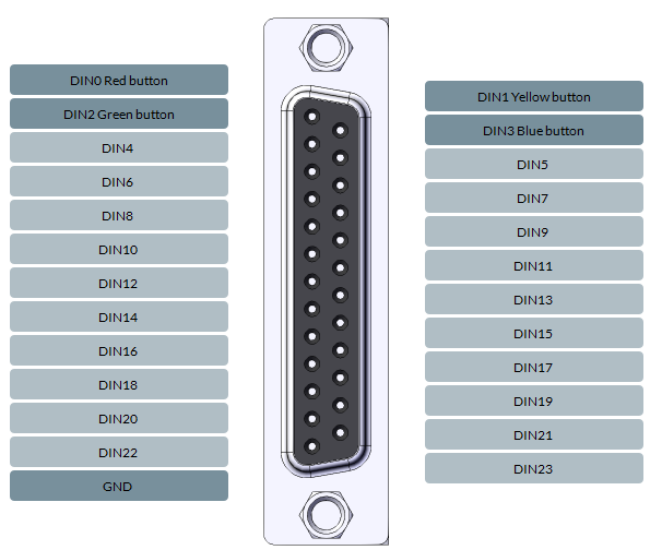
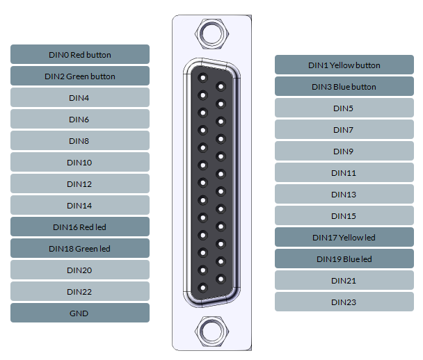
Digital IN Port
Available with:
-
VIEWPixx Monitor
-
DATAPixx2
-
DATAPixx3
-
PROPixx Controller
Individual Pin Signal
A digital pulse can be simulated on each of the 25 pins of the DB25 port. Simply click on the desired pin to reveal the Signal property, and select Digital Pulse.
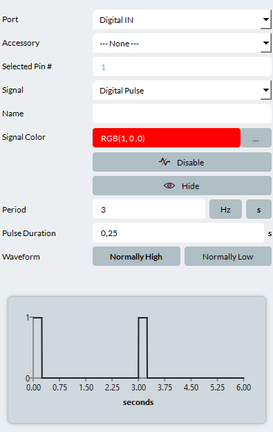
You can edit the following properties:
-
Name: The name tied to the signal. Useful to mark what this signal is tied to in your experiment.
-
Signal Color: The colour of the signal. This will change the colour of this signal curve on the Signal Viewer.
-
Disable: Toggle this to disable this signal during simulation.
-
Hide: Toggle this to hide the signal during a simulation.
-
Period: The total cycle length of your digital pulse. Includes both the on/off durations. Period can be specified in Hz or seconds
-
Pulse Duration: The duration of your pulse signal in seconds.
-
Waveform: Choose between Normally High (Pulse value of 1, rest value of 0) and Normally Low (Pulse value of 0, rest value of 1).
A signal preview is shown at the bottom of the Properties panel, allowing you to confirm your signal has the desired shape.
Accessories
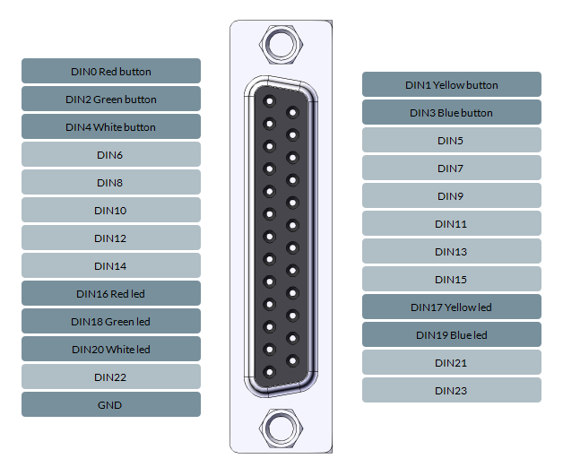
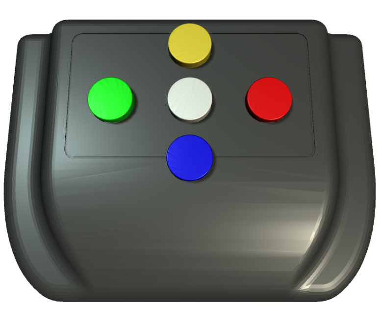
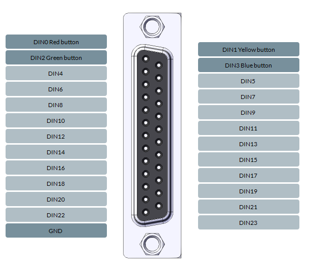
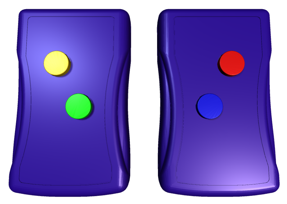
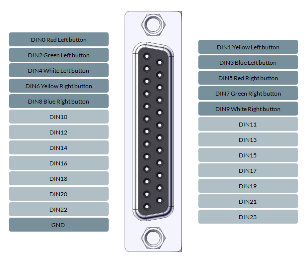
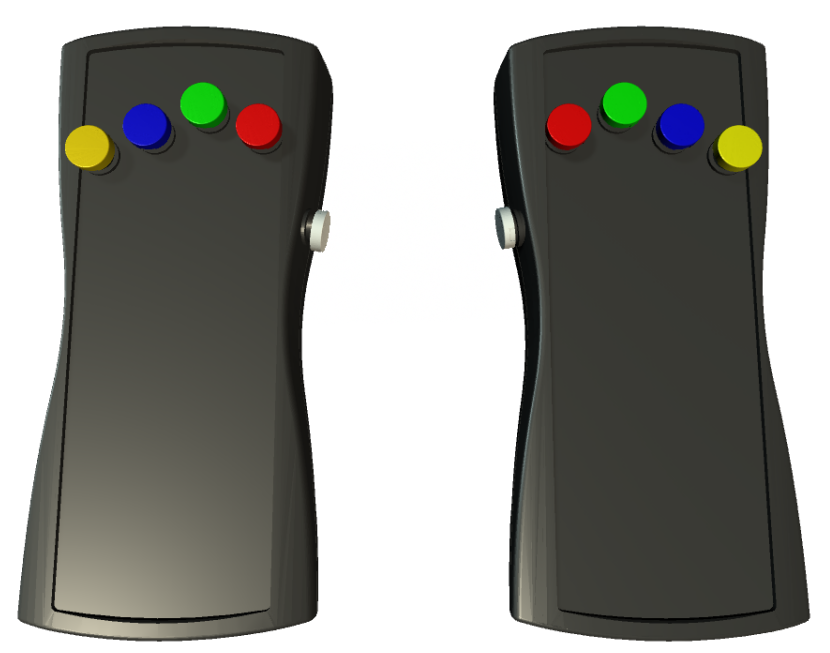
Various RESPONSEPixx devices can be simulated on the Digital IN port. When doing so, the DB25 Pins will automatically be configured to replicate the behaviour of the selected device, and an additional tab will appear at the top left of the simulator window, also named after the connected accessory. This additional window (illustrated below for all respective devices) allows you to simulate inputs on these devices using the computer mouse. These inputs are reflected in the signal viewer and behave similarly to inputs from real devices.
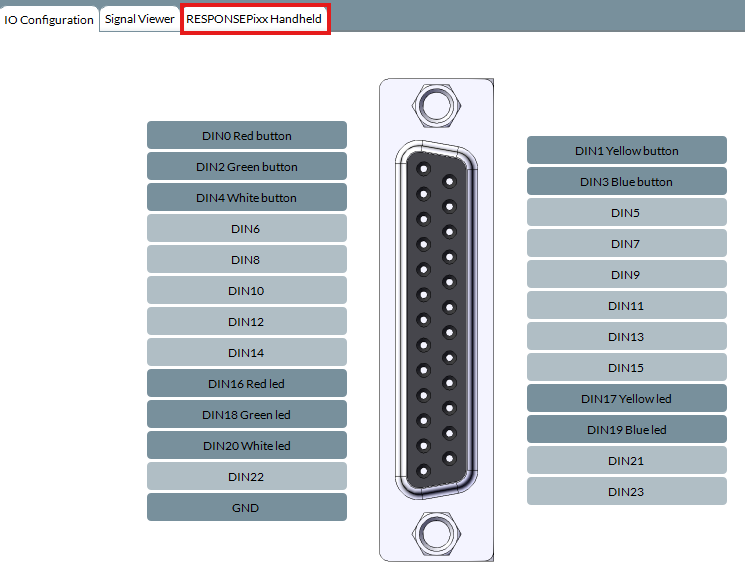
The following RESPONSEPixx devices are compatible with the Hardware simulator:
RESPONSEPixx Handheld/MRI
RESPONSEPixx Handheld - MRI
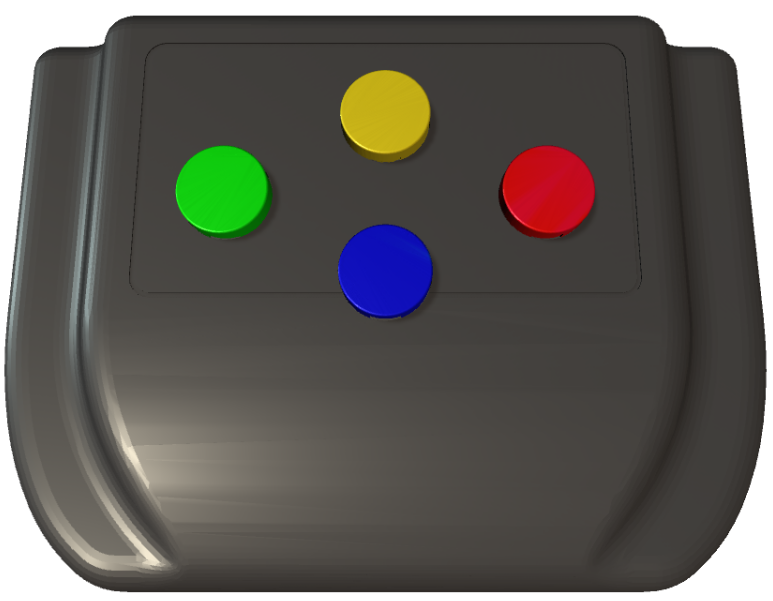
RESPONSEPixx Dual Handheld
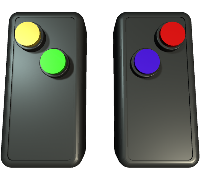
RESPONSEPixx Dual - MRI
RESPONSEPixx MRI 10 Buttons
Digital OUT
Available with:
-
VIEWPixx Monitor
-
DATAPixx2
-
DATAPixx3
-
PROPixx Controller
Individual Pin Signal
A digital output can be simulated on each of the 25 pins of the DB25 port. Simply click on the desired pin to reveal the Signal property, and select Output.
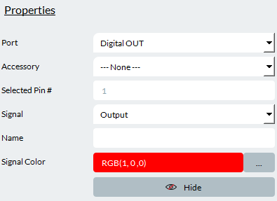
You can edit the following properties:
-
Signal Color: The colour of the signal. This will change the colour of this signal curve on the Signal Viewer.
Accessories
No Digital Output accessories are currently supported by the LabMaestro Hardware Simulator.
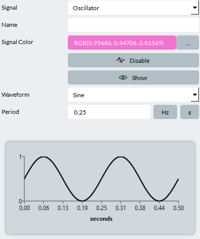
Analog I/O
Available with:
-
VIEWPixx Monitor
-
DATAPixx2
-
DATAPixx3
-
PROPixx Controller
Individual Pin Signal
An analog oscillator can be simulated on 16 of the 25 pins of the DB25 port. Simply click on the desired pin to reveal the Signal property, and select Oscillator.
-
Name: The name tied to the signal. Useful to mark what this signal is tied to in your experiment.
-
Signal Color: The colour of the signal. This will change the colour of this signal curve on the Signal Viewer.
-
Enable/Disable: Toggle this to enable/disable this signal during simulation.
-
Show/Hide: Toggle this to show/hide the signal during a simulation.
-
Waveform: Choose the type of signal waveform you wish your signal to take. You can choose between Sine, Square, Triangle, or Sawtooth.
-
Period: The total cycle length of your digital pulse. Includes both the on/off durations. Period can be specified in Hz or seconds
A signal preview is shown at the bottom of the Properties panel, allowing you to confirm your signal has the desired shape.
VideoBahn
Available with:
-
DATAPixx3
TRACKPixx3
By simulating a TRACKPixx 3, you can simulate eye movements during an experiment using your mouse. Press Start Signal to enable your simulated tracker.
For LabMaestro to properly detect your simulated tracker, make sure to wake your device and perform a calibration.
PROPixx
By simulating a PROPixx projector, you can access and edit your hardware's configuration to fit project requirements.
Thank you for your interest in this feature. This page is presently under construction. If you have any further questions, please reach out to our support team at support@vpixx.com