Overview
This page details how to configure the RESPONSEPixx for use within LabMaestro and how to use the LabMaestro Hardware Simulator to simulate it.
Before you begin, you should:
-
Have LabMaestro installed and running
-
Have a DATAPixx / I/O hub powered on and connected to your PC via USB
-
Have your RESPONSEPixx device connected to the Digital In port of the DATAPixx / I/O hub
-
Be familiar with the Environment and Devices Overview
Configure the device in your environment
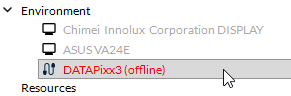
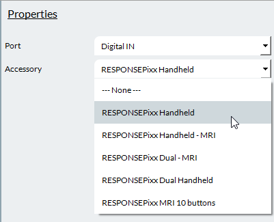
Before using your Digital Input device, you must add your DATAPixx3 to your project. Your DATAPixx3 should automatically be detected by LabMaestro. You can see it under the Environment section of the Project panel. Double-click on the device under the Environment to open the Device Settings menu. You can add the device to your project by right-clicking it or by using the properties window.
If your device is not automatically detected by the LabMaestro software, please ensure it is powered on and connected to your computer. Also, please ensure your DATAPixx firmware is up to date.
Simulating a RESPONSEPixx with the LabMaestro Hardware Simulator
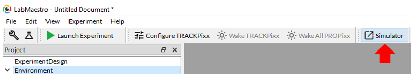
To simulate a RESPONSEPixx, you must first simulate a DATAPixx3. Start by launching the LabMaestro Hardware Simulator by clicking the “Simulator” button.
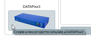
After the simulator has launched, under “New Project”, select the DATAPixx3 to create a new project simulating a DATAPixx3.
Once your DATAPixx3 is simulated, you can simulate a RESPONSEPixx device through the Digital IN port.
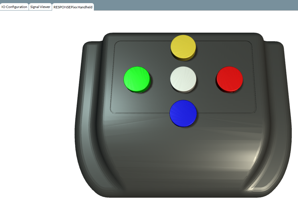
This will add a third tab to the top left of the simulator window, allowing you to interact with the simulated RESPONSEPixx device. Pressing one of the device’s buttons through this window will simulate a button press on a real device.
Once your device is simulated, you can add the simulated DATAPixx3 to your LabMaestro project.
Linking Button Inputs to Events
You can use your real or simulated RESPONSEPixx to record inputs via Command Components such as Listen for Inputs and Wait for Inputs.
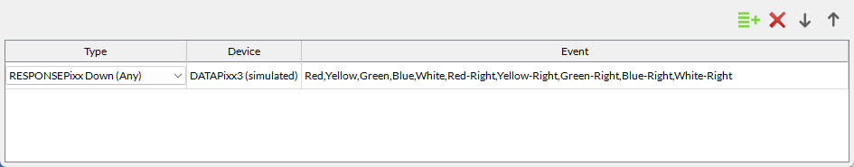
After adding such a component to your timeline, using the Inputs property, do the following:
-
For Type, select the corresponding to your RESPONSEPixx device (either RESPONSEPixx or RESPONSEPixx MRI, Up or Down inputs).
-
For Device, select your real/simulated device to which your RESPONSEPixx device is connected.
-
For Event, select the accepted inputs on your device (ex. Red, Green for the red and green buttons).
RESPONSEPixx Inputs in Log Files
After you have exported your recording, you can access your data for more in-depth analyses. For each trial, your input will be recorded in a column named after your input recording component (e.g., WaitForInput). Each input will be linked to an Experiment Time and a Trial Time.
-
The Experiment Time represents the number of seconds elapsed since the beginning of the experiment.
-
The Trial Time represents the elapsed time since the beginning of the trial; if your target appears at the beginning of a trial, 0.0 corresponds to the target onset. You can also use the Reset Timer component alongside the target onset to ensure your reaction time measurement is accurate.
The recorded input value is stored as a Digital Input Value; this means the reported value equals 2 raised to the power of the Digital Pin position (2DIN). You can read more on this on this page: A Comprehensive Guide to RESPONSEPixx Button Boxes .
For reference, here are the input values for a single button press for all buttons on a standard RESPONSEPixx:
|
Button |
Value |
|---|---|
|
Red (DIN 0) |
1 (20) |
|
Yellow (DIN 1) |
2 (21) |
|
Green (DIN 2) |
4 (22) |
|
Blue (DIN 3) |
8 (23) |
|
White (DIN 4) |
16 (24) |