
This page is for the first and second generations of the DATAPixx devices (DATAPixx and DATAPixx2). If you are looking for information on setting up a DATAPixx3 with LabMaestro, please see this page.
Overview
This page covers how to configure and use older DATAPixx (DATAPixx/DATAPixx2) I/O Hub hardware in LabMaestro, as well as how to simulate a DATAPixx2 in the device simulator.
Before you begin, you should:
-
Have LabMaestro installed and running
-
Have the DATAPixx powered on and connected to your PC via USB
-
Be familiar with the Environment and Devices Overview
Configure the device in your environment
Your DATAPixx device should be automatically detected by LabMaestro at startup. You can see it under the Environment section of the Project panel. Double-click on the device under the Environment to open the Device Settings menu. You can add the device to your project by right-clicking it or by opening the properties window.
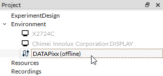
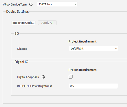
If your device is not automatically detected by the LabMaestro software, please ensure it is powered on and connected to your computer. Also, please ensure your DATAPixx firmware is up to date.
DATAPixx Properties
|
Setting |
Description |
Options |
|---|---|---|
|
3D |
||
|
Glasses |
Select the type of 3D glasses to use when VIEWPixx /3D is set to one of its 3D video modes. See the following guide to familiarize yourself with 3D Stimulus Presentation with the VIEWPixx /3D |
|
|
Digital IO |
||
|
Digital Loopback |
Enable/disable the internal digital loopback between the digital inputs and outputs (each digital output channel sends its output to the corresponding digital input channel, e.g., DOUT 0 → DIN 0, DOUT 1 → DIN 1, etc.). |
Enable or Disable (default = disabled) |
|
RESPONSEPixx Brightness |
Set the LED brightness on the buttons of a standard RESPONSEPixx button box connected to the digital input. |
0.0-1.0 (default = 0.0) |
DATAPixx2 Properties
|
Setting |
Description |
Options |
|---|---|---|
|
3D |
||
|
Glasses |
Select the type of 3D glasses to use when VIEWPixx /3D is set to one of its 3D video modes. See the following guide to familiarize yourself with 3D Stimulus Presentation with the VIEWPixx /3D |
|
|
Phase |
Select the phase of the VESA 3D waveform that drives the 3D glasses; adjust this value to minimize cross-talk. |
0-255 (default = 100) |
|
Audio |
||
|
Audio Output Volume |
Define the volume of audio signals sent from the DATAPixx3. |
0-1 (default = 0.1) |
|
Onboard Speaker Volume |
Define the speaker volume. |
0-1 (default = 1.0) |
|
Digital IO |
||
|
Digital Loopback |
Enable/disable the internal digital loopback between the digital inputs and outputs (each digital output channel sends its output to the corresponding digital input channel, e.g., DOUT 0 → DIN 0, DOUT 1 → DIN 1, etc.). |
Enable or Disable (default = disabled) |
|
RESPONSEPixx Brightness |
Set the LED brightness on the buttons of a standard RESPONSEPixx button box connected to the digital input. |
0.0-1.0 (default = 0.0) |
|
Output Mode |
Select the digital output mode. The “Normal” mode is the standard setting for Digital Output; the user may set digital output values “manually” or use schedules to output digital waveforms. Pixel Mode enables automated 24-bit digital output triggers based on the RGB channel values of the top-left pixel. Pixel Mode GB enables automated 16-bit digital output triggers based on the GB channel values of the top-left pixel. |
|
|
Video |
||
|
Mode |
Set the device’s rendering mode. See the following guide on the different 3D modes available: 3D Stimulus Presentation with the VIEWPixx /3D
|
|
Simulating a DATAPixx2 with the LabMaestro Hardware Simulator
Simulation of the first-generation DATAPixx is not supported by the LabMaestro Hardware simulator.
To simulate a DataPixx2, you will first need to launch the LabMaestro Hardware Simulator by clicking the “Simulator” button.

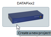
After the simulator has launched, under “New Project”, select the DATAPixx2 to create a new project simulating a DATAPixx2.
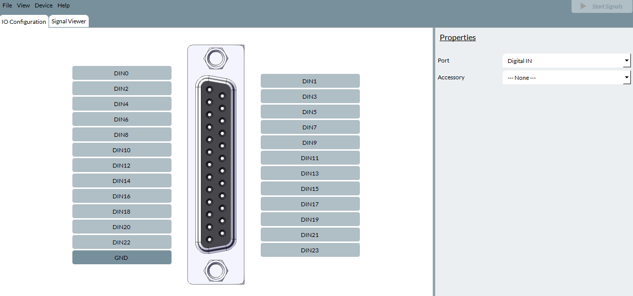
The simulated DATAPixx2 device can emulate the I/O capabilities of a physical device, including Digital Input, Digital Output, and Analog I/O. The properties of these simulated features can be configured in the “IO Configuration” tab:
For general information on simulating devices and I/O signals, see Simulator Device Types and Coverage