This page provides information on the 3DPixx kit sold after 2019, which uses Volfoni EDGE glasses. Kits sold prior to 2019 use NVIDIA 3D glasses, which are now discontinued. The old user manual for the NVIDIA kit is available here.
Product Overview
The 3DPixx kit includes two pairs of 3D EDGETM VR glasses and an ActiveHubRF50TM RF emitter.
The system is designed to function with your VIEWPixx /3D, PROPixx Controller or DATAPixx I/O hub to allow 3D stereoscopic viewing. Features include:
-
Ultra-fast-response liquid crystal lenses for superior image quality
-
No silver screen required
-
Image quality preserved at all seating positions
-
Bright 3D images and natural colours
-
Easy-to-clean frames
-
Adjustable arms in 3 sizes
-
Best-in-class liquid crystal lenses with high contrast and light efficiency
-
Stable images even at long-range (5 m)
-
RF synchronization avoids interference from other wireless devices
-
Programmable
-
Automatic power-off function saves energy
This page describes the connection and setup procedures as well as the operation of the EDGETM VR glasses and ActiveHubRF50TM RF emitter. Compliance, safety and warranty information can be found at the bottom of the page.
Product Details
3D EDGETM VR glasses
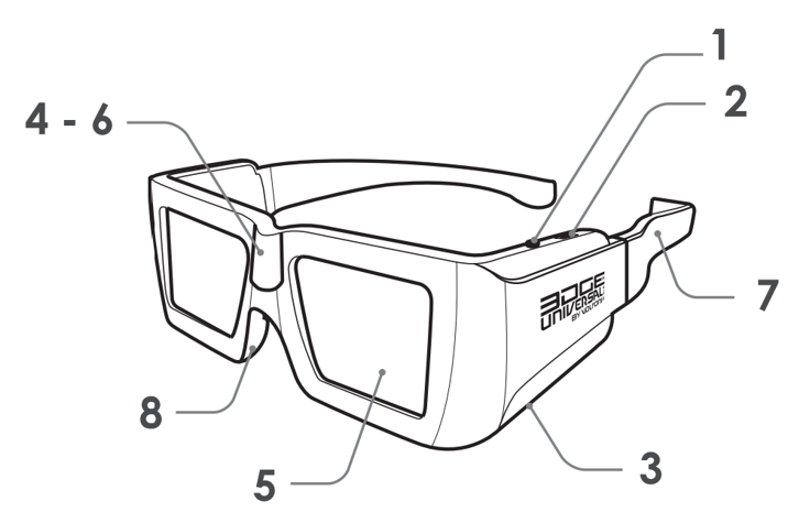
RF 3D glasses are active (i.e., they require power) and use radio frequency technology to synchronize with and receive data from the RF emitter. A labelled diagram of the glasses is shown below:
-
ON/OFF button
-
Programmable 3-position switch
-
MicroUSB port
-
RF receiver
-
Liquid crystal lenses
-
LED status light
-
Interchangeable arms
-
Rubberized nosepiece
ActiveHubRF50TM RF emitter
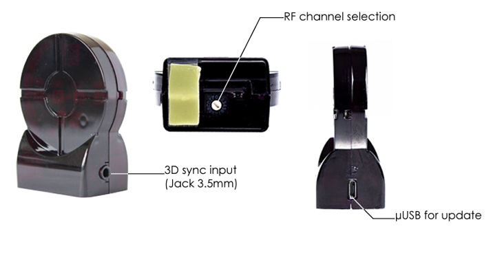
The RF emitter receives both power and a 3D synchronization signal from a VESA-DIN3 cable connected to your VPixx hardware. The emitter wirelessly transmits the synchronization signal in the RF band to the 3D active glasses to control shutter behaviour. The emitter can also be connected to a PC via micro USB for firmware updates, as needed.
Assembly and Installation
Your 3DPixx kit includes the following:
-
RF emitter with VESA cable
-
Glasses (2 pairs)
-
3 sets of removable arms (S, M, L)
-
Micro USB charging cable
-
Microfiber cleaning wipe
The glasses are fragile. Care should be taken to avoid dropping or scratching the lenses during installation and use.
Product assembly - Glasses
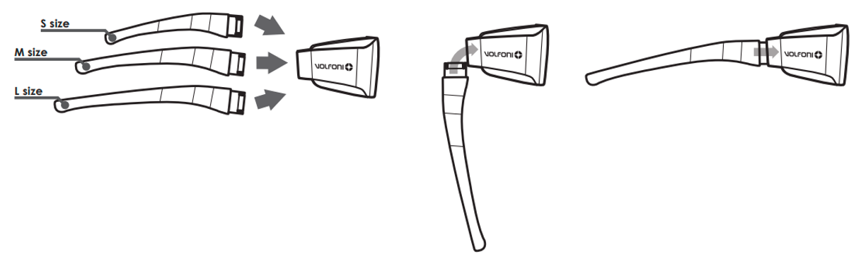
The glasses come with three interchangeable sets of arms (small, medium, and large sizes). To change the arms, slide each arm onto the side of the shutter glass frame, as shown below, until you feel the unit click. Select and assemble the arms that best fit the participant’s head size.
Product assembly - Connecting the RF emitter
The RF emitter must:
-
Have a clear line of sight to the intended location where the 3D glasses will be used
-
Rest on a stable surface
Typically, placing the emitter on or near the base of your display is sufficient to ensure reliable transmission. Once you have verified a good signal, consider using double-sided tape to secure the emitter in place.
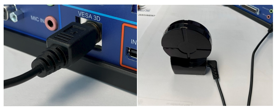
To connect the emitter to a VIEWPixx display or DATAPixx3 video I/O hub, insert the rectangular end of the emitter cable into the port labelled VESA 3D on the back of the VPixx device. The other end of the cable is a 3.5mm jack, which is connected to the RF emitter’s 3D sync input.
Product Usage
Powering on the glasses
Press the ON/OFF button on the side of the glasses to turn them on. The left and right lenses will each flash once in sequence to indicate to the user that the glasses are powered on. Hold down the ON/OFF button to turn the glasses off.
The glasses will automatically turn off in the following cases:
-
No movement of the glasses for 5 minutes
-
Loss of RF synchronization for 10 minutes.
Charging the glasses
Ensure the glasses are fully charged before use. To charge the glasses, connect the glasses to a power supply via the provided mircoUSB cable. When the glasses are connected to a power source, the LED on the side of the frame will show the battery charging status:
|
LED status |
Information |
|
Steady light |
Charging |
|
OFF |
Charging complete |
When the glasses are not connected to a power supply, the user can press down the switch (#2 in the figure above) to verify the current battery level. The level is indicated by the number of times the LED on the glasses blinks.
|
LED status |
Information |
|
One flash |
Low battery level (less than 30%) |
|
Two flashes |
Battery level between 30% and 90% |
|
Three flashes |
Battery level higher than 90% |
RF emitter connectivity
Once powered, the RF emitter automatically checks for synchronization sources such as VESA, DLP-Link and IR. If one of these signals is detected, the RF emitter will focus exclusively on it until its next full power cycle. To switch to another synchronization source, you must power off the RF emitter. The scan priority order is:
-
Wired 3D signal
-
DLP-link 3D signal
-
IR 3D signal
The channel selection dial on the bottom of the emitter should be set to 8 for use with VPixx products. See Product Usage - Advanced configuration options using Volfoni Loader for more details on changing the RF channel using Volfoni software.
The blue LED on the emitter reflects the current state of the device:
|
LED status |
Information |
|
OFF |
No power |
|
Solid |
The RF emitter is powered but is not receiving a synchronization signal |
|
Blinking |
The RF emitter is powered and receiving a VESA 3D synchronization signal |
Test patterns
Test patterns are simple demonstrations of VPixx products. They are preloaded onto VPixx hardware and do not rely on your graphics card or experiment code. They are used to quickly visualize product features and validate system performance, independent of your PC.
Some VPixx devices have test patterns that can be accessed by remote control. For access to all device test patterns, open the LabMaestro application, right-click on the device in the Environment section of the Project pane, and select Test Patterns from the menu. This will open the Test Pattern widget.
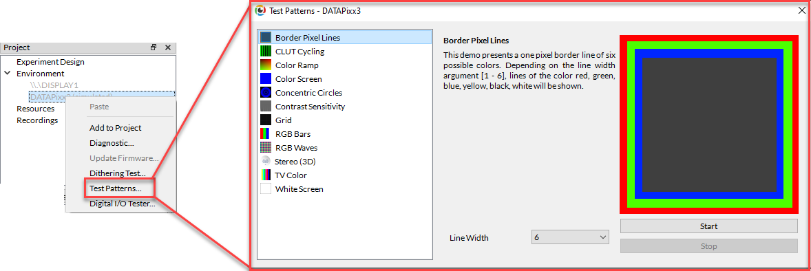
Only test patterns suitable for your selected device will appear in the widget. Each test pattern includes an explanation of the pattern and an example of expected behaviour. Some test patterns include options to adjust the pattern parameters. While a test pattern is enabled, your device will be unresponsive to typical user behaviour (e.g., mouse clicks). Stop the test pattern to return to regular operation.
LabMaestro 1.11 is currently supported under Windows and Linux. MacOS support will be implemented soon. To access test patterns in macOS, open the vputil application and type ‘tp’ to see options.
The 3DPixx has two associated Test Patterns that you can use to verify the 3D features are working:
-
3D Pictures Slideshow: This Test Pattern shows six different high-resolution static 3D images, which demonstrate the 3D capabilities of your hardware. It is compatible with both the 3DPixx and 3DPolarizer accessories. Specific images can be selected by passing a number from 1-6 as the second argument in the VPutil tp command.
-
Stereo Goggles: This Test Pattern presents alternating green and red stimuli. Viewers not wearing 3D glasses will see a temporally fused, static yellow screen. On the right side of the image a sequence of gray lines are each presented in only one of the two eyes. This Test Pattern is compatible with both the 3DPixx and 3DPolarizer accessories.
Using 3D in your experiments
By default, the RF emitter will not send a 3D signal to the glasses unless you use a Test Pattern or manually set your VPixx hardware to be in one of our 3D presentation modes. When in a supported 3D mode, the RF emitter will drive the glasses synchronized to your display refresh rate.
To learn more about our different supported 3D modes and how to set up a 3D experiment using the 3DPixx, see our tutorial: 3D Stimulus Presentation with the VIEWPixx /3D. This tutorial includes several experiment code examples you can use and modify to suit your needs.
Advanced configuration options using Volfoni Loader
Volfoni Loader is a free software tool that can be used to fine-tune the performance of 3DPixx according to the specific needs of the researcher. With the IR emitter and glasses connected to your PC via their respective micro USB connections, you can:
-
Adjust the glasses' shutter speed to optimize for brighter stimuli vs. minimized crosstalk
-
Configure the programmable switch on the side of the glasses (e.g., to reverse left and right lens behaviours)
-
Change the RF channel (e.g., to accommodate RF noise or other emitters)
For more details on the loader and to download the application, see http://volfoni.com/en/support-2/.
Product Specifications
RF emitter
-
Signal range: 30 m (98 ft)
-
Frequency: 2.4 GHz frequency (ISM band)
RF glasses
-
Weight: 56 g
-
Rechargeable glasses / Battery life: 75 hours
|
Specification |
Value |
|
Sync operation |
Radio-Frequency |
|
Frequency |
2.4Ghz |
|
Refresh rate compatibility |
all refresh-rates up to 220Hz |
|
Optical Transmission |
38% |
|
Residual light |
18.5% |
|
Contrast |
> 940:1 (no ghosting) |
|
Chromacity |
Color correction not mandatory |
|
Weight |
56 g |
|
Autonomy |
75 hours of usage |
|
Range |
5 m |
|
Operating temperature |
0°C ~ +40°C (32F-104F) |
|
Storage temperature |
-10°C ~ +50°C (14F-122F) |
|
Certification |
CE certified |
Cleaning and Maintenance
Do not use cleaners that contain any petroleum-based materials such as benzene, thinner, or any other volatile substance to clean any part of this product.
Do not soak or immerse the product in liquid, as it is an electronic device that can be damaged or impaired by moisture. Do not apply pressure to, impact, or rub the sensitive product surface.
The 3DPixx consists of an IR emitter and two pairs of active 3D shutter glasses. The emitter can be cleaned with a soft cloth dipped in warm, soapy water. The shutter glasses should be cleaned and disinfected between uses as they come in direct contact with the participant’s face. We recommend wiping down the plastic frame with disinfectant wipes, or a cloth dampened with disinfectant. The lenses can be cleaned with a damp microfiber cloth and a small amount of gentle soap.
Troubleshooting your Device
Below are some possible issues you can encounter when using the 3DPixx system. These issues may appear with both Test Patterns and manual control of the 3DPixx.
|
Issue |
Solution |
|---|---|
|
The image flickers in the RF glasses |
Ensure there is no other wireless devices using the same RF band (2.4 GHz) within 30 meters of the RF emitter |
|
Shadows/banding on the upper or lower portion of the display, visible in one or both eyes |
VESA phase is not properly aligned with screen refresh. Ensure you have set the correct VESA phase and waveform for your glasses type in your experiment (see this section of our tutorial). If the issue persists you may also wish to use the Volfoni Loader to configure shutter timing for longer/shorter aperture times. |
|
Glasses appear to stop working after ~20 seconds |
The glasses are not receiving a reliable 3D signal. Verify the issue does not happen with Test Patterns, then investigate your experiment code. |
|
The image blinks when I turn on the RF glasses. |
The battery is low. Please recharge the glasses. |
Related Links
-
Volfoni Loader and Technical Support - http://volfoni.com/en/support-2/
Compliance, Safety and Warranty Information
Click on the sections below to expand the relevant information.
Compliance Information
For the United States of America
This device complies with part 15 subpart B of FCC rules. Its operation is subject to the following two conditions: (1) this device may not cause harmful interference, and (2) this device must accept any interference received, including interference that may cause undesired operation. This equipment has been tested and found to comply with the limits for a Class A digital device, pursuant to part 15 subpart B of the FCC rules.
For Canada
This Class A digital apparatus complies with Canadian ICES-003.
CISPR warning: This is a Class A product. In domestic environments this product may cause radio interference in which case the user may be required to take adequate measures.
For European Countries
DECLARATION OF CONFORMITY
|
|
Manufacturer’s Name:
Manufacturer’s Address:
|
|
Product Name: 3DPixx
|
|
|---|---|
|
2014/30/EEC
|
Electromagnetic Compatibility directive
|
|
|
SUPPLEMENTARY INFORMATION
To remain CE compliant, only CE compliant parts should be used with this product. Maintaining CE compliance also requires proper cable and cabling techniques. VPixx Technologies will not retest systems or components that have been modified by customers. Signature: 
|
The following information is only for EU member states:

|
The mark shown to the left is in compliance with the Waste Electrical and Electronic Equipment directive 2012/19/EU (WEEE). The mark indicates the requirement NOT to dispose of the equipment as unsorted municipal waste. For more information call VPixx Technologies Inc. or email us at support@vpixx.com |
Declaration of RoHS Compliance
|

|
This product has been designed and manufactured in compliance with Directive 2015/863/EU of the European Parliament and the Council on the restriction of the use of certain hazardous substances in electrical and electronic equipment (RoHS Directive). |