The VIEWPixx3 /OLED user manual is still under development. If you have any questions, please contact our support team at support@vpixx.com.
Product Overview
The VIEWPixx3 /OLED is a 27" research-grade display designed specifically for vision science and psychophysics. It combines a calibrated OLED panel with integrated data I/O, digital triggering, and tight software integration, so the same device can serve as both your primary stimulus display and a hardware hub.
Key characteristics:
-
High-resolution OLED panel: 2560 × 1440 (QHD, 16:9) at 120 Hz for detailed, flicker-free stimuli.
-
Native 10-bit colour: Smooth gradients and precision colour control
-
Extremely high contrast: Deep blacks and bright whites for low- and high-luminance work
-
Dedicated Research Mode: Disables consumer OLED features for precise visual stimulation
-
Linearized Gamma: Toggle between standard (2.2) and linear gamma curves for flexible display properties
-
DisplayPort 1.3 video with a secondary DisplayPort console output to mirror the stimulus display
-
Full software ecosystem, including LabMaestro configuration, MATLAB and Python APIs.
The VIEWPixx3 /OLED is available as a standalone display or as part of turnkey research packages that bundle a DATAPixx3 video I/O hub, TRACKPixx3 eye tracker, RESPONSEPixx control pad and other accessories for visual neuroscience. This user manual is solely focussed on the VIEWPixx3 /OLED display. For information on our other devices, please see our hardware documentation hub.
Product Details
The monitor
This section describes the main physical interfaces of the VIEWPixx3 /OLED. Expand the relevant section to view details about the device subsystem, including technical specifications and pin assignment.
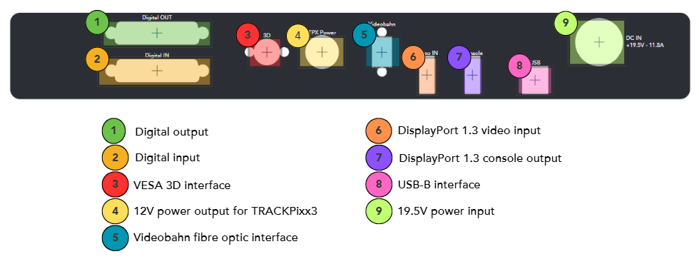
1. Digital output
Digital output
The 24-channel TTL sends automated triggers synchronized to the video stream via Pixel Mode (see below). Common use cases include event marking for EEG/MEG systems, stimulus onset triggers for eye trackers, and synchronization with external acquisition hardware.
Technical specifications:
-
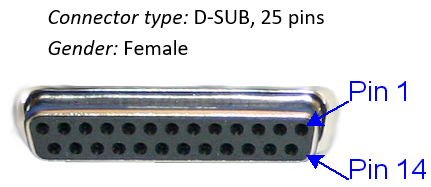
24 digital outputs on DB25 connector (female)
-
Output drive stage: 5 V through 25 Ω series resistor
-
Maximum output current:
-
Source: 15 mA
-
Sink: 12 mA
-
Detailed pin assignment information:
Below are the industry standard pin labels and their corresponding function. Pins 1-12 are configured for even digital output channels from 0-22; pins 12-25 are configured for odd digital output channels from 1-23; pin 13 is ground. Note that pin numbering follows the industry standard for DB25 ports.
|
Pin |
Description |
Pin |
Description |
|
|
1 |
Digital Out 0 |
14 |
Digital Out 1 |
|
|
2 |
Digital Out 2 |
15 |
Digital Out 3 |
|
|
3 |
Digital Out 4 |
16 |
Digital Out 5 |
|
|
4 |
Digital Out 6 |
17 |
Digital Out 7 |
|
|
5 |
Digital Out 8 |
18 |
Digital Out 9 |
|
|
6 |
Digital Out 10 |
19 |
Digital Out 11 |
|
|
7 |
Digital Out 12 |
20 |
Digital Out 13 |
|
|
8 |
Digital Out 14 |
21 |
Digital Out 15 |
|
|
9 |
Digital Out 16 |
22 |
Digital Out 17 |
|
|
10 |
Digital Out 18 |
23 |
Digital Out 19 |
|
|
11 |
Digital Out 20 |
24 |
Digital Out 21 |
|
|
12 |
Digital Out 22 |
25 |
Digital Out 23 |
|
|
13 |
GND |
Shield * |
||
*Shield is tied to the GND by a 0 Ohm resistor inside the VIEWPixx.
2. Digital input
Digital input
The 24-channel TTL input is intended for accessories and external synchronization signals such as response pad input or MRI triggers. Inputs are recorded on the same hardware clock as video timestamps, supporting precise alignment of inputs with stimulus delivery.
Technical specifications:
-
24 inputs on DB25 connector (female)
-
Input termination: >20 kΩ pull-up to 3.3 V
-
Input tolerance: 5 V
Detailed pin assignment information:
Below are the industry standard pin labels and their corresponding function. Pins 1-12 are configured for even digital input channels from 0-22; pins 12-25 are configured for odd digital input channels from 1-23; pin 13 is ground. Note that pin numbering follows the industry standard for DB25 ports.
|
Pin |
Description |
Pin |
Description |
|
|
1 |
Digital In 0 |
14 |
Digital In 1 |
|
|
2 |
Digital In 2 |
15 |
Digital In 3 |
|
|
3 |
Digital In 4 |
16 |
Digital In 5 |
|
|
4 |
Digital In 6 |
17 |
Digital In 7 |
|
|
5 |
Digital In 8 |
18 |
Digital In 9 |
|
|
6 |
Digital In 10 |
19 |
Digital In 11 |
|
|
7 |
Digital In 12 |
20 |
Digital In 13 |
|
|
8 |
Digital In 14 |
21 |
Digital In 15 |
|
|
9 |
Digital In 16 |
22 |
Digital In 17 |
|
|
10 |
Digital In 18 |
23 |
Digital In 19 |
|
|
11 |
Digital In 20 |
24 |
Digital In 21 |
|
|
12 |
Digital In 22 |
25 |
Digital In 23 |
|
|
13 |
GND |
Shield * |
||
*Shield is tied to the GND by a 0 Ohm resistor inside the VIEWPixx /3D.
3. VESA 3D interface
VESA 3D interface
The VIEWPixx3 \OLED’s VESA 3D interface enables 3D stimulus presentation on the display. A VESA-compliant system like the 3DPixx must be connected to use 3D features.
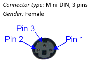
Detailed pin assignment information:
Below are the industry standard pin labels and their corresponding function.
|
Pin |
Description |
|
|
1 |
+5 VDC ** |
|
|
2 |
GND |
|
|
3 |
VESA_LR (+5 VDC) |
|
|
Shield* |
||
*Shield is tied to the GND by a 0 Ohm resistor inside the VIEWPixx /3D.
**Current limited (400mA).
9. 12V power output for TRACKPixx3
12V power output for TRACKPixx3
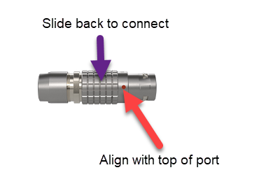
The VIEWPixx3 /OLED provides 12V DC power to the TRACKPixx3 eye tracking camera and illuminator via this port. It uses an 8-pin LEMO connector. LEMO connectors have a small orange dot indicating which side of the connector should point upwards. The textured metal ring around the connector slides back for cable insertion. Ensure the connector is firmly attached to the port during operation.
Technical specifications
-
Stable +12V DC on 8-pin LEMO connector
-
Maximum power output is 108 Watts (9 A)
Please do not unplug the VIEWPixx3 /OLED’s power cord while the monitor is active. Make sure the device is turned off (LED indicator red) before doing so.
The front panel and LED indicators
The table below summarizes the VIEWPixx3 /OLED master power button behaviour and the meanings of the front-panel LED indicators.
|
Signal / Pattern |
Meaning |
Notes / Duration |
|---|---|---|
|
Master Power Button |
||
|
Always ON |
Consumer Mode |
— |
|
Always OFF |
Research Mode |
— |
|
3 long flashes |
Maintenance activation request |
Maintenance starts after 10 seconds (if not interrupted). |
|
LED Status (Green) |
||
|
3 short flashes |
Maintenance Mode activated |
Approx. 4 minutes |
|
2 short flashes (no repeat) |
IR command received |
Confirms remote/IR input. |
|
LED Fault (Red) |
||
|
1 short flash |
Digital output short circuit |
Fault condition. |
|
2 short flashes |
Fan malfunction |
Fault condition. |
|
3 short flashes |
Temperature fault |
Fault condition. |
The remote control
Below is an image of the remote control for the VIEWPixx3 \OLED, with a table of buttons and their functions.

|
Button |
Function |
|---|---|
|
ON |
Power on the monitor |
|
OFF |
Power off the monitor |
|
Up arrow |
Not assigned |
|
Down arrow |
Not assigned |
|
Right arrow |
Not assigned |
|
Left arrow |
Not assigned |
|
Enter |
Not assigned |
|
STBY |
Not assigned |
|
Mode RSCH |
Enables Research Mode |
|
Mode CONS |
Enables Consumer Mode |
|
GAMMA LINEAR |
Sets the gamma curve of the monitor to be linear (gamma = 1.0) |
|
GAMMA 2.2 |
Sets the gamma curve of the monitor to be like a standard monitor (gamma = 2.2) |
|
CUSTOM A |
|
|
CUSTOM B |
|
|
<- |
Previous test pattern |
|
-> |
Next test pattern |
Test patterns are images loaded into the VIEWPixx3 /OLED hardware. They can be accessed by toggling the → and ← arrows at the bottom of the remote. These are useful particularly when installing and troubleshooting the monitor, as they do not require a video connection to the PC.
|
Test pattern |
Description |
|---|---|
|
None |
Normal operating mode; requires a video signal from the PC |
|
More coming soon |
|
A full list of all test patterns for your system, including descriptions and images of the expected pattern appearance, are available in LabMaestro by right-clicking the device in the Environment pane, then selecting Test Patterns.
System Requirements
The following section outlines the software and hardware requirements for the PC connected to the VIEWPixx3 /OLED display.
VPixx Software Tools
VPixx Software Tools is a package of APIs and high-level software tools for use with VPixx products. It contains everything you need to connect to, configure and operate our devices from your experiment PC. It includes the following:
-
LabMaestro, a program designed by VPixx Technologies for configuring VPixx hardware and designing/implementing experiments.
-
Datapixx.mex, a library of commands for use with MATLAB/Psychtoolbox and VPixx products
-
pypixxlib, a library of Python tools for VPixx products
The latest version of VPixx Software Tools can be downloaded directly from our website at any time. Support documentation, tutorials, and demos for all of our software tools can be found on our support site: https://docs.vpixx.com/
Supported operating systems
VPixx Software Tools are developed and supported under Windows, macOS and Linux (Ubuntu) operating systems. For an up-to-date list of supported OS versions visit Software Download & Information.
Recommendations for experiment PCs and graphics cards
We regularly receive questions about what experiment PC characteristics and graphics cards we recommend for use with our hardware. Generally speaking, most modern machines and GPUs (i.e., from the last 5 years) should be compatible with our devices. The following minimum video output must be supported:
-
PROPixx projector, VIEWPixx LCD Series: 1920 x 1080 resolution, 120 Hz refresh
-
VIEWPixx3 /OLED: 2560 × 1440 resolution, 120 Hz refresh
Unfortunately, we are not able to exhaustively test commercially available systems and make specific recommendations regarding makes/models.
Recommendations for video adapters
Please use one of the following video protocols from your PC:
-
DisplayPort
-
DisplayPort mini/Thunderbolt
-
USB-C to DisplayPort
We do not recommend converting from other video protocols (e.g., HDMI or VGA) as this can have unpredictable consequences for display behaviour.
Assembly and Installation
What’s included with your product
-
Monitor
-
Stand for monitor
-
AC adapter and power cord, with international adapter set
-
10-foot USB-B to USB-A cable
-
10-foot DisplayPort to DisplayPort cable
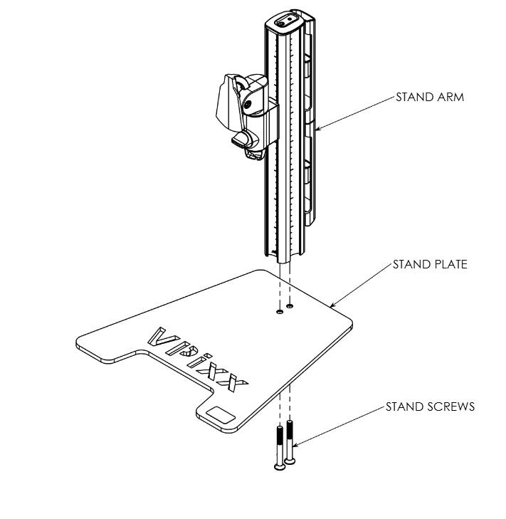
Product assembly - Installing the monitor on the stand
-
Attach the stand arm to the stand plate, and secure it in place using the provided stand screws and 5 mm allen key.
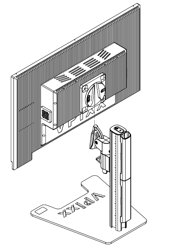
2. Slide the monitor into the stand anchor on the stand arm, until you hear a ‘click’
Product assembly - Connecting the monitor to your PC
Use the cables provided with your order. Do NOT substitute cables of unknown origin. If you require longer cables than what has been provided, contact support@vpixx.com for assistance.
Unlike a commercial display, the VIEWPixx3 /OLED has a video connection and a USB connection to the experiment PC. When the monitor is successfully connected, you should detect the VIEWPixx3 /OLED as a connected USB device in your Device Manager and as a display in your system display settings.

-
Connect the VIEWPixx3 /OLED monitor’s 19.5V power input to a suitable power source using the provided cable and AC adapter.
-
Connect the VIEWPixx3 /OLED monitor USB-B port to a USB port on your experiment PC.
-
Connect the VIEWPixx3 /OLED DisplayPort cable to a suitable DisplayPort output on your PC. Ensure this DisplayPort is driven by your graphics card, not your onboard graphics processor. Onboard graphics are considerably less powerful and will result in suboptimal video output.
-
[Optional] Connect the console monitor to the DisplayPort console port on the side of the VIEWPixx3 /OLED.
Product Usage
Warm-up time
To ensure stable operating temperature, uniformity, and luminance, warm up the VIEWPixx3 /OLED before data collection by displaying a full-screen white image in Research Mode for at least 45 minutes after bootup.
Consumer vs. Research Modes
Even with a state-of-the-art cooling system, the VIEWPixx3 /OLED still uses commercial OLED protection features to help protect the panel and extend its lifespan. Because these features can affect stimulus presentation, the display provides two operating modes:
|
Mode |
Description |
Visual indicator |
Recommended usage |
|---|---|---|---|
|
Consumer Mode |
Consumer-grade OLED protections enabled for everyday use |
Flashing red square in the top-left corner of the display |
Default mode outside data collection |
|
Research Mode |
Protections and video modifications disabled. Pixel values are unmodified, and pixel response time is optimized. |
Power button is not illuminated |
Experiments and data collection |
Research Mode disables customary OLED screen protections; therefore it is critical that is not be left on for extended periods of time.
To protect the screen’s integrity and prevent accidental long-duration operation, Research Mode operates on a timer.
Research Mode is limited to 2 hours total. After this, you will need to briefly revert the display to Consumer Mode, then you can re-enable Research Mode.
After 6 hours of operation in any combination of Research and Consumer Modes, the display needs to run a maintenance routine. See the section below labelled “Maintenance Mode” for details.
How to keep the unit in Research Mode
-
Remote control: Pressing the RSCH button toggles on the mode for up to 15 minutes per request.
-
LabMaestro:
-
During an experiment: Research Mode is automatic—it turns on when the experiment starts and turns off when it ends.
-
While LabMaestro is open: Can be configured via project settings. LabMaestro will auto-renew the activation every 15 minutes until the 2 hour limit is reached.
-
-
APIs (MATLAB/Python): The user must issue an activation request every 15 minutes (until the 2-hour limit is reached). See code examples below.
After calling API commands on the experiment PC, you must explicitly communicate them to VPixx hardware:
-
Register writes push pending commands from the computer to the device
-
Register updates (aka write-reads) push commands to the device and read back the latest device state.
If you skip these calls, commands may not take effect and status reads may be outdated. See The Logic of VPixx Hardware Control for more details.
Custom Power-Off Sequence
The VIEWPixx3 /OLED uses a power-off sequence that differs from a consumer display.
-
When you press the green Power button (or OFF on the remote), the power button flashes for 10 seconds.
-
During this 10-second window, pressing the power button again will cancel the shutdown and immediately restart the device.
-
If the button is not pressed again after 10 seconds, the monitor enters Maintenance Mode. During Maintenance mode, the device is unavailable.
Maintenance Mode takes approximately 4 minutes and helps maintain the long-term stability of the VIEWPixx3 /OLED.
Maintenance Mode
Maintenance Mode is an internal calibration mode that is run frequently on the display to preserve its longevity and stability. Maintenance Mode is automatically triggered under the following circumstances:
-
If the monitor has been on for >6 hours in Consumer Mode or a combination of Consumer Mode and Research Mode;
-
Whenever the monitor is powered down, and not immediately restarted.
Display Gamma Options
The gamma characterizes the relationship between the pixel values sent to the display and the output luminance, according to the function L = Vγ , where L is the output luminance, V is the input value of the pixel (typically expressed as a value from 0-1 or 0-255), and γ is the gamma exponent.
Modern commercial displays typically have a gamma of 2.2 or more, meaning that, in practice, the luminance output of the display does not increase linearly with the input values specified by the user. This has significant consequences for vision science paradigms where stepwise increments of light values are needed.
The VIEWPixx3 /OLED supports two gamma curve profiles:
|
Mode |
Gamma Value |
Description |
Visual Indicator |
|---|---|---|---|
|
Standard |
2.2 |
Consumer typical output, e.g., for movies or standard viewing. |
Bright colours appear more saturated due to non-linearity |
|
Linear |
1 |
Linear mapping of pixel value to output. No software gamma correction required. |
Bright colours appear more pale |
How to set the display Gamma
-
Remote control: Set gamma to LINEAR or 2.2 using the buttons
-
In LabMaestro, double-click on the VIEWPixx3 /OLED in the Environment pane to open the device settings. Navigate to the bottom and select the gamma from the drop-down menu.
-
APIs (MATLAB/Python): See commands below.
After calling API commands on the experiment PC, you must explicitly communicate them to VPixx hardware:
-
Register writes push pending commands from the computer to the device
-
Register updates (aka write-reads) push commands to the device and read back the latest device state.
If you skip these calls, commands may not take effect and status reads may be outdated. See The Logic of VPixx Hardware Control for more details.
Maximum Luminance
The VIEWPixx3 /OLED allows you to set a luminance target between 0 and 200 cd/m2. When this value is set, a white screen at the maximum value will have this luminance.
How to set the Maximum Luminance (software only)
-
In LabMaestro, double-click on the VIEWPixx3 /OLED in the Environment pane to open the device settings. Navigate to the bottom and enter your target luminance in cd/m2 in the provided field.
-
APIs (MATLAB/Python): See commands below.
After calling API commands on the experiment PC, you must explicitly communicate them to VPixx hardware:
-
Register writes push pending commands from the computer to the device
-
Register updates (aka write-reads) push commands to the device and read back the latest device state.
If you skip these calls, commands may not take effect and status reads may be outdated. See The Logic of VPixx Hardware Control for more details.
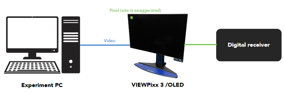
Digital Outputs (Pixel Mode)
The VIEWPixx3 /OLED sends automated digital signals, aka ‘triggers,’ based on the colour of the top left pixel on the display. These signal are locked to video frame onset with deterministic timing and microsecond precision. You can learn all about this feature in this guide: Sending Triggers with Pixel Mode. Use our Pixel Mode pixel value calculator to determine what pixel values you should use for your desired output. Trigger cabling to your receiver is sold separately.
Digital Inputs
The VIEWPixx3 /OLED can record digital inputs from button boxes and external triggers. For more information see our guide:
3D applications
The VIEWPixx3 /OLED has a VESA-standard 3D port, which can be used with the 3DPixx active shutter glasses kit (sold separately) to display 3D stimuli. There are several video modes available for formatting 3D stimuli with this system; for a comprehensive guide and demos, see this guide:
Product Specifications
OLED panel characteristics
For a summary of OLED panel characteristics, including resolution, physical size, contrast ratio, pixel pitch and more, see our product datasheet.
Driving the VIEWPixx3 /OLED with a DATAPixx3 Video I/O Hub
You can use a DATAPixx3 video I/O hub to drive the VIEWPixx3 /OLED and unlock advanced features. Specific configuration and specifications for this combination of devices is given below. For general information regarding the DATAPixx3 signalling capabilities, see our DATAPixx3 User Manual.
Thank you for your patience as we continue to update this guide. More information will be added to this section soon.
Cleaning and Maintenance
Before lifting or moving the monitor, disconnect all cables and the power cord. Use proper lifting techniques, and carry the monitor by the edges of the display—never by the stand or the cables.
Turn off the monitor and unplug it before cleaning. Wipe the screen gently with a lint-free, non-abrasive cloth. For stubborn marks, use a cloth lightly dampened with a mild, screen-safe cleaner. Do not use cleaners that contain alcohol or acetone, and never spray liquid directly onto the screen. When cleaning an OLED module, do not allow any liquid to enter the gap around the edge of the panel, as this may cause abnormal operation or damage.
Commercial cleaning products or disinfectants may be used on the stand, frame, and cables. Apply the product to a soft cloth (not directly to the hardware) and wipe as needed. Clean ports using compressed air.
Troubleshooting your Device
|
Issue |
Solution |
|---|---|
|
The screen is not turning back on after being turned off |
The VIEWPixx3/OLED is in Maintenance Mode. Wait 5 minutes for the unit to finish and then restart the device. |
|
Red flashing square in corner of screen |
Display is in Consumer Mode. No troubleshooting required. Use the remote or software tools to switch to Research Mode for experiment/data collection periods. |
|
Display not detected |
Try the following:
|
Related Links
Compliance, Safety and Warranty Information
Click on the sections below to expand the relevant information.
Compliance Information
For the United States of America
This device complies with part 15 subpart B of FCC rules. Its operation is subject to the following two conditions: (1) this device may not cause harmful interference, and (2) this device must accept any interference received, including interference that may cause undesired operation. This equipment has been tested and found to comply with the limits for a Class A digital device, pursuant to part 15 subpart B of the FCC rules.
For Canada
This Class A digital apparatus complies with Canadian ICES-003.
CISPR warning: This is a Class A product. In domestic environments this product may cause radio interference in which case the user may be required to take adequate measures.
For European Countries
DECLARATION OF CONFORMITY
|
|
Manufacturer’s Name:
Manufacturer’s Address:
|
Product Name: VIEWPixx Full, VIEWPixx Lite, VIEWPixx /3D Full, VIEWPixx /3D Lite, VIEWPixx XL-48 Lite, VIEWPixx XL-48 Full, VIEWPixx /EEG
Part Numbers: VPX-VPX-2001C, VPX-VPX-2000A, VPX-VPX-2005D, VPX-VPX-2004B, VPX-VPX-2010A, VPX-VPX-2011C, VPX-VPX-2006B
Product Options : All
Application of Council Directive:
2014/30/EEC -Electromagnetic Compatibility directive
2015/863/EU -Restriction of Hazardous Substances Directive
2012/19/EU -Waste Electrical and Electronic Equipment directive
|
|
SUPPLEMENTARY INFORMATION
To remain CE compliant, only CE compliant parts should be used with this product. Maintaining CE compliance also requires proper cable and cabling techniques. VPixx Technologies will not retest systems or components that have been modified by customers. Signature: 
|
The following information is only for EU member states:

|
The mark shown to the left is in compliance with the Waste Electrical and Electronic Equipment directive 2012/19/EU (WEEE). The mark indicates the requirement NOT to dispose of the equipment as unsorted municipal waste. For more information call VPixx Technologies Inc. or email us at support@vpixx.com |
Declaration of RoHS Compliance
|

|
This product has been designed and manufactured in compliance with Directive 2015/863/EU of the European Parliament and the Council on the restriction of the use of certain hazardous substances in electrical and electronic equipment (RoHS Directive). |