
Product Overview
RESPONSEPixx button boxes offer a microsecond-precise method of collecting participant responses in lab and neuroimaging settings. Button presses are detected as TTL transitions on the digital input of a dedicated FPGA sampling at 1 MHz. The timestamp is captured at the moment of the electrical transition, providing microsecond-accurate response-time measurement on the same hardware clock that timestamps your visual stimulus onset and other VPixx peripherals.
Connecting the RESPONSEPixx to a DATAPixx3, VIEWPixx or PROPixx gives you microsecond-precise response times, with a reliability that exceeds USB-based response boxes. Each of the RESPONSEPixx buttons can be illuminated under software control, and can cue subjects during forced-choice paradigms. The RESPONSEPixx uses medical grade silicone cables, resulting in maximum flexibility and durability. Custom button box layouts and button colours are also available.
For a comprehensive guide to using RESPONSEPixx button boxes in your experiments — including DIN log usage, polling, debounce, DIN code interpretation, masking, and code examples — see the RESPONSEPixx VOCAL Guide.
Product Details
There are six standard RESPONSEPixx models, divided into two families: electrical (wired) units for standard lab environments and MRI (fiber optic) units for use inside magnetically shielded rooms. The two families use opposite polarity conventions; see the sections below for details.
To find your product code, refer to your invoice or shipment packing list.
Model overview
|
Product code |
Name |
Buttons |
Connection |
Product page |
|---|---|---|---|---|
|
Electrical units |
|
|
|
|
|
VPX-ACC-3100 |
RESPONSEPixx Handheld |
5 buttons |
DB-25 (wired) |
|
|
VPX-ACC-3000 |
RESPONSEPixx Dual Handheld |
2×2 buttons |
DB-25 (wired) |
|
|
VPX-ACC-3050 |
RESPONSEPixx Tabletop |
5 buttons |
DB-25 (wired) |
|
|
MRI units (fiber optic) |
|
|
|
|
|
VPX-ACC-4910 |
RESPONSEPixx /MRI Handheld |
4 buttons |
Fiber optic |
|
|
VPX-ACC-4900 |
RESPONSEPixx /MRI Dual |
2×2 buttons |
Fiber optic |
|
|
VPX-ACC-4920 |
RESPONSEPixx /MRI Dual 5-Button |
2×5 buttons |
Fiber optic |
Assembly and Installation
This section provides connection instructions for both electrical and MRI RESPONSEPixx units. Navigate to the section for your unit type.
Connecting electrical units
Electrical RESPONSEPixx units (Handheld, Dual Handheld, Tabletop) connect directly to the DB-25 Digital Input port on your VPixx I/O hub (DATAPixx3, PROPixx Controller, or VIEWPixx series monitor).
Connect the RESPONSEPixx DB-25 cable to the female connector labelled Digital In on your VPixx device. No additional hardware or power supply is required.
Polarity convention: On electrical units, channels are HIGH by default (value of 1). A button press pulls the channel LOW (value of 0). The idle state reads as all 1s.
DB-25 pin assignment (electrical units)
|
DB-25 Pin |
Assignment |
VPixx Digital Input |
|---|---|---|
|
1 |
Red button |
DIN 0 |
|
14 |
Yellow button |
DIN 1 |
|
2 |
Green button |
DIN 2 |
|
15 |
Blue button |
DIN 3 |
|
3 |
White button * |
DIN 4 |
|
9 |
Red LED |
DIN 16 |
|
22 |
Yellow LED |
DIN 17 |
|
10 |
Green LED |
DIN 18 |
|
23 |
Blue LED |
DIN 19 |
|
11 |
White LED * |
DIN 20 |
White button/LED is not implemented on all models.
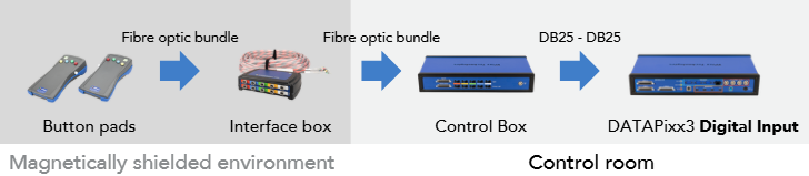
Connecting MRI units (fiber optic)
Warning: Fiber optic cables are fragile! Please use extra caution and do not bend or force the cabling.
MRI RESPONSEPixx units use fiber optic cables to transmit button signals from the MRI suite to a control box in the control room. The control box converts the fiber optic signals back to electrical TTL and forwards them to the DATAPixx3 via a DB-25 cable.
Polarity convention: On MRI units, channels are LOW by default (value of 0). A button press pulls the channel HIGH (value of 1). This is the opposite polarity to electrical units.
Code written for an electrical unit will not work for an MRI unit without adjusting the press-detection logic. If your code checks for a channel going LOW, it will never see a press on an MRI unit. See the Troubleshooting section for common polarity-related issues.
What's included (MRI kit)
|
Qty |
Item |
Description |
|---|---|---|
|
1x |
Button box(es) |
Plastic response box(es) for participant input |
|
1x |
Control pad interface |
Interface unit for the handheld response boxes (fiber optic connection) |
|
1x |
Control box |
Receives the fiber optic bundle and provides the DATAPixx interface connection |
|
1x |
DB25 cable |
Connects the control box to the DATAPixx3 Digital In port |
Installation
-
Place the left- and right-hand button boxes with the participant, and place the control pad interface in a stable location inside the MR suite.
-
Pass the fiber optic bundle through a suitable data waveguide on the penetration panel and into the control room.
-
Connect the colour-coded connectors in the fiber optic bundle to the labelled ports on the back of the control box.
-
Connect the control box to a power source. Depending on your model, this may be an external power supply or the 12 V power output on the DATAPixx3 unit.
-
Connect the DB25 port labelled DATAPixx interface on the control box to the Digital In port on the DATAPixx3 control unit.
DB-25 pin assignment (MRI control box to DATAPixx3)
|
DB-25 Pin |
VPixx Digital Input |
Notes |
|---|---|---|
|
1 |
DIN 0 |
Left hand — Red |
|
14 |
DIN 1 |
Left hand — Yellow |
|
2 |
DIN 2 |
Left hand — Green |
|
15 |
DIN 3 |
Left hand — Blue |
|
3 |
DIN 4 |
Left hand — White |
|
16 |
DIN 5 |
Right hand — Red |
|
4 |
DIN 6 |
Right hand — Yellow |
|
17 |
DIN 7 |
Right hand — Green |
|
5 |
DIN 8 |
Right hand — Blue |
|
18 |
DIN 9 |
Right hand — White |
|
13 |
GND |
Ground |
Pin-to-button assignments shown are for the 10-input (Dual 5-Button) control box. For 4-input control boxes (Handheld and Dual models), only DIN 0–3 are populated.
Product Usage
Electrical units
Connect the RESPONSEPixx DB-25 cable to the Digital In port on your VPixx I/O hub (DATAPixx3, PROPixx Controller, or VIEWPixx series monitor). No additional hardware or power is required.
To test the unit, open LabMaestro, right-click on your device in the Environment panel, and select Digital I/O Tester. Press each button and verify which DIN channel changes state. Use those channels in your experiment code.
Electrical units have built-in LEDs behind each button that can be controlled via the digital output. You can light up individual buttons to cue valid responses, provide feedback, or run interactive games. To use them, set the appropriate digital output pins using Datapixx('SetDinDataDirection') and write to the corresponding DOUT channels. See the Simon Game demo for a complete example with illuminated buttons, audio cues, and reaction time measurement.
MRI units (fiber optic)
MRI units require a multi-step cabling path:
The control box requires 12 V power, typically supplied from the DATAPixx3's LEMO 12 V output. See the Assembly and Installation section above for step-by-step cabling instructions.
Once cabled, open LabMaestro and use the Digital I/O Tester to verify your button-to-DIN mapping. MRI units use the opposite polarity to electrical units (LOW idle, HIGH on press), so code written for electrical units must be adjusted. See the Troubleshooting section for common polarity-related issues.
MRI button pads do not have illuminated LEDs. The LED feedback feature is only available on electrical units.
Product Specifications
Electrical units
|
Specification |
VPX-ACC-3100 (Handheld) |
VPX-ACC-3000
|
VPX-ACC-3050 (Tabletop) |
|---|---|---|---|
|
Buttons |
5 thumb buttons |
2×2 thumb buttons |
5 large buttons |
|
Dimensions |
14 × 10.2 × 3.5 cm |
10 × 5.8 × 2.85 cm |
23.3 × 13.34 × 6 cm |
|
Cable length |
3.66 m (12 ft) |
3.66 m (12 ft) |
3.66 m (12 ft) |
|
Connector |
DB-25 |
DB-25 |
DB-25 |
|
Illuminated buttons |
Yes |
Yes |
Yes |
|
Timing precision |
Microsecond |
Microsecond |
Microsecond |
MRI units
|
Specification |
VPX-ACC-4910 (Handheld) |
VPX-ACC-4900 (Dual) |
VPX-ACC-4920 (Dual 5-Button) |
|---|---|---|---|
|
Buttons |
4 buttons |
2×2 buttons |
2×5 buttons |
|
Connection |
Fiber optic |
Fiber optic |
Fiber optic |
|
Control box |
Required |
Required |
Required (10-input) |
|
MR safety |
MR Safe (button pads) |
MR Safe (button pads) |
MR Safe (button pads) |
|
Timing precision |
Microsecond |
Microsecond |
Microsecond |
Cleaning and Maintenance
Clean the surface of your RESPONSEPixx as required and depending on usage. Do not use cleaners that contain any petroleum-based materials such as benzene, thinner, or any volatile substance to clean the RESPONSEPixx. Use a soft cloth with gentle soap or standard disinfectant wipes.
For MRI units, handle fiber optic cables with care. Do not bend, kink, or force the cabling. Store the fiber optic bundle loosely coiled to avoid damage.
Troubleshooting your Device
|
Issue |
Solution |
|---|---|
|
Button presses aren't being detected |
Most common cause: wrong DIN channel assumption. Open the LabMaestro Digital I/O Tester and press each button to verify which channel changes state. Never hardcode DIN values from someone else's setup. |
|
Code hangs waiting for button input |
Polarity mismatch between code and hardware. Code written for an electrical unit (expects HIGH→LOW) will hang on an MRI unit (sends LOW→HIGH). Verify your unit type and adjust press-detection logic. |
|
Double-presses / phantom events in the DIN log |
Debounce not enabled. Enable with: |
|
Button codes don't match documentation |
Other devices connected to the digital input are changing the idle state. Use bitwise AND with a mask that covers only your button channels. |
|
MRI trigger isn't being detected |
Wrong DIN channel for the trigger. The trigger channel depends on control box wiring (commonly DIN 10 or DIN 15). Use the Digital I/O Tester while the scanner sends a trigger to find the correct channel. |
|
Buttons are physically sticking or jamming |
Known issue on some MRI button pads. Contact support@vpixx.com for warranty assessment. |
Related Links
Compliance, Safety and Warranty Information
Click on the sections below to expand the relevant information.
Safety and Warnings
Safety precautions
This device is intended solely for research purposes and is not suitable for medical applications or diagnostic use.
MRI safety indicators
The following table shows MR safety warning indicators and their names and meanings. Please pay special attention to the symbols on your equipment, and obey all guidelines to protect staff and equipment from injury.
|
Symbol |
Name |
Description |

|
MR safe |
Components marked with the green MR safe indicator present no danger to staff and equipment operating in the MR room. |

|
Conditionally MR safe |
The yellow Conditionally MR safe indicator denotes components that are only MR safe in a limited fashion. Product-specific safety requirements apply. For additional details, consult the product manual's safety section. |

|
MR unsafe |
The red MR unsafe indicator denotes components prohibited from entering the MR room. |