Product Overview
The VPX-TRK-3410C TRACKPixx3 eye tracker consists of the following core components:
-
A TRACKPixx3 camera
-
A mounting apparatus
-
All required cables
-
A 27” LCD console monitor
In addition to these components, as part of your order, you will have also received:
|
Component |
Description |
Options |
|---|---|---|
|
Camera lens (1x) |
The lens and IR filter that attaches to the camera body |
VPX-ACC-1180 (25 mm short-range)
|
|
Infrared illuminator (1x) |
IR lamp that illuminates the participant’s face |
VPX-TRK-9000 (850 nm short-range)
|
|
Control unit (1x) |
Dedicated VPixx hardware that manages eye tracking data |
VPX-DPX-1005C DATAPixx3 video I/O Hub
|
|
Chinrest (optional) |
Configurable chinrest for fixing the participant’s head during tracking |
VPX-ACC-1150 Chinrest |
The exact options provided will depend on the requirements of your installation, the species you are tracking, and your testing needs. These will have been discussed with a VPixx staff scientist as part of your sales consultation.
This guide provides key information about your eye tracking system, installation tips, data format and access, and links to in-depth resources for using your eye tracker.
-
For detailed system specifications, see our TRACKPixx3 product datasheet.
-
For general usage within LabMaestro software, see: Using the TRACKPixx3 within LabMaestro
-
For calibrating the tracker, see: TRACKPixx3 Calibration Walkthrough
Product Details
This guide concerns the eye tracking system specifically; for data acquisition and display features associated with your control unit (DATAPixx3 or VIEWPixx3 /OLED) please see their respective user manuals.
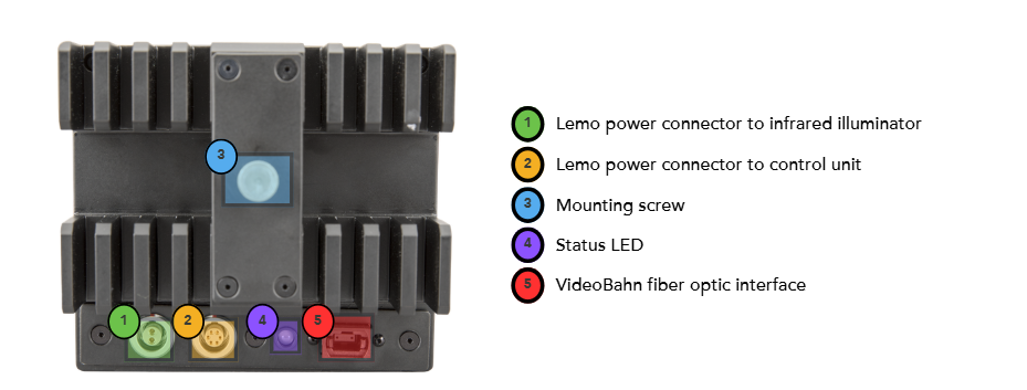
The camera
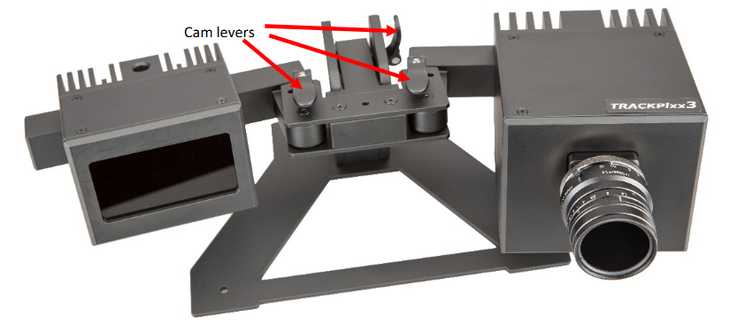
The mounting apparatus - Tabletop
Below is an image of the mounting apparatus for the tabletop version of the TRACKPixx3. The camera levers are indicated with arrows; these levers can be used to adjust the yaw of illuminator and camera body separately, and the pitch of the armature supporting these two elements.
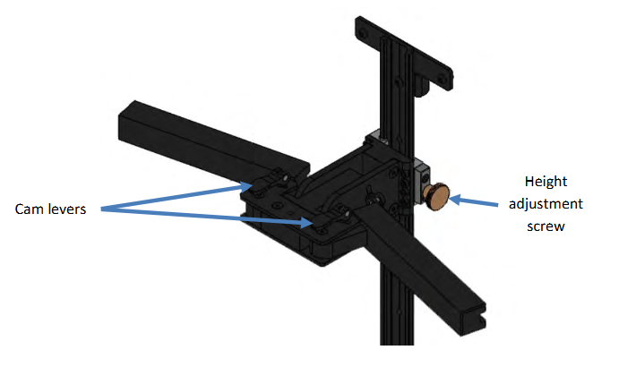
The mounting apparatus - Freestanding
In some installations, particularly where a PROPixx projection screen is used, the tabletop arm support is replaced with a freestanding arm mount. This is pictured below, with the camera levers identified with arrows:
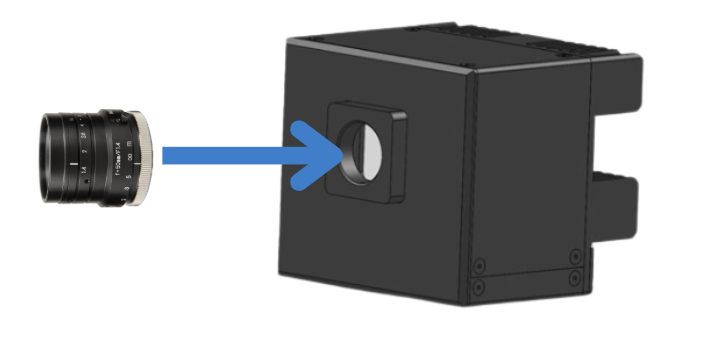
The camera lens
The camera lens is shipped in a separate box to protect the optics. It can be mounted on the camera body and screwed into place. The focus adjustment and aperture are indicated with arrows.
The aperture is used to control the amount of light that passes through the lens to the sensor; the focus adjusts the sharpness of the image.

The console monitor
Your TRACKPixx3 installation includes a 27” LCD monitor that can be used as a console display. The console shows a copy of the main experiment display and a live feed of the camera view, without adding load to the experiment PC’s graphics processor. The console is typically placed within the experimenter’s station for real-time monitoring of the participant. The layout of the camera feed and experiment display can be configured in LabMaestro → TRACKPixx3 → Device Settings.
|
Display |
Description |
Use case |
|---|---|---|
|
Stimulus Display 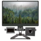
|
The screen that presents all visual stimuli and instructions to the participant |
Main experiment display |
|
Console Display 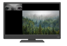
|
A secondary monitor that shows a copy of the experiment and a live eye tracking camera feed |
Participant and experiment monitoring (e.g., from the control room) |
Cable guide
Below are images of the cables provided in your order, with close-up images of the connectors and usage notes.
|
Cable type |
Connector type |
Connects from → to |
Notes |
|---|---|---|---|
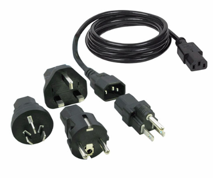
International power cord |
Various |
Console monitor adapter → power source |
- |
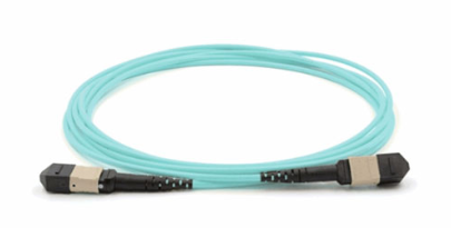
Fiber optic data cable |
Fiber optic |
Control unit → tracker camera (see #5 in labelled camera diagram) |
Grey panel slides back during attachment; should make an audible click when seated properly. FRAGILE; DO NOT BEND |
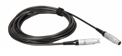
Power cord |
Lemo |
Control unit → tracker camera (#2 in labelled camera diagram) |
The metal shank can be slid back to facilitate seating. Orange dot on the top of the connector aligns with dot on port. |
Cabling associated with components not included in VPX-TRK-3410C kit are described in their respective manuals.
System Requirements
VPixx Software Tools is a package of APIs and high-level software tools for use with VPixx products. It contains everything you need to connect to, configure and operate our devices from your experiment PC. It includes the following:
-
LabMaestro, a program designed by VPixx Technologies for configuring VPixx hardware and designing/implementing experiments.
-
Datapixx.mex, a library of commands for use with MATLAB/Psychtoolbox and VPixx products
-
pypixxlib, a library of Python tools for VPixx products
The latest version of VPixx Software Tools can be downloaded directly from our website at any time. Support documentation, tutorials, and demos for all of our software tools can be found on our support site: https://docs.vpixx.com/
Supported operating systems
VPixx Software Tools are developed and supported under Windows, macOS and Linux (Ubuntu) operating systems. For an up-to-date list of supported OS versions visit Software Download & Information.
Assembly and Installation
What’s included:
-
1/8” allen wrench
-
27” LCD monitor (console display)
-
AC adaptor and power cord (for console display)
-
Fiber optic data cable
-
Camera power interface cable
-
TRACKPixx3 camera box
-
TRACKPixx camera mount
Assembling the camera
We suggest assembling the camera on a clean, stable surface. Unpackage the lens and screw it onto the sensor mount on the front of the camera box. Do not over-tighten.
Placing the camera and illuminator on the mount
The camera and illuminator both have slots on the back that allow them to slide onto the arms of the camera mount. It does not matter which component is placed on which arm. Select the configuration that allows the easiest access to the camera lens without reaching in front of the illuminator, as the lens needs to be adjusted manually during calibration:

Once the camera and illuminator are in position, tighten the mounting screws (bronze-coloured screws on the back of the camera and the iluminator; #2 in the labelled image of the camera above). This holds the components in place.
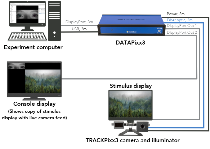
Typical layout - with DATAPixx3 controller
Below is a typical installation for a tabletop tracking scenario with a DATAPixx3 controller. Note: the power cable between the camera and illuminator is not shown.
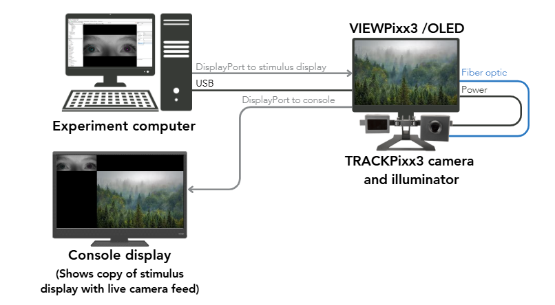
Typical layout - with VIEWPixx3 /OLED display
Below is a typical installation for a tabletop tracking scenario in which the tracker is directly connected to the VIEWPixx3/OLED monitor. Note: the power cable between the camera and illuminator is not shown.
Step-by-step installation
Use the following guide to ensure all connections for the eye tracking system have been established.
-
Connect the power cable between the illuminator and the camera (Tip: the textured metal shank on the lemo connector slides back for easier connection. The orange dot on the top of the connector aligns with the dot on the port).
-
Connect the power cable between the camera and the control unit
-
Connect the fiber optic cable between the camera and the control unit
-
Connect the control unit to a power source (like a wall outlet)
-
Connect the control unit to your PC via USB and DisplayPort cable (Tip: the DisplayPort input to the control unit should insert into the port labelled Video Input or Video In 1)
-
[Optional] Connect the console monitor to the video output on the control unit
-
Power on the control unit. The status LED on the back of the camera should flash red, then orange.
Product Usage
The TRACKPixx3 requires 15 minutes of warm-up time after power up before use. This warm-up period will ensure the best image and tracking quality.
Accessing your tracker in software
Start by installing the latest version of VPixx Software Tools: Software Download & Information.
Once you have installed our software, power on the control unit by pressing the power button (if it is not already on). On your PC, open the LabMaestro application and create a new empty project. Find your control unit in the Project menu, under the Environment tab, and double-click it to open your settings widget.
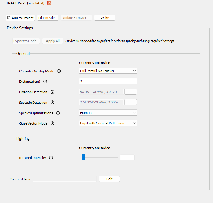
You can use this widget to modify settings on the camera, such as:
-
Configure saccade and fixation flag parameters
-
Configure the console display layout
-
Add a tracking distance
-
Specify the species being tracked
-
Set infrared illuminator intensity
Next, you can acces the camera view by clicking on Configure Tracker in the menu at the top of the application. You can configure the camera viewer settings in this section, wake the tracker, view the camera live feed, run a calibration, and enable recording in this interface.
For more details, please refer to Using the TRACKPixx3 within LabMaestro. You can find a full list of tracker settings here: TRACKPixx3 Calibration Walkthrough | Appendix I: List of tracker and calibration settings.
Ready to get started? Try our LabMaestro calibration project here and collect some data: TRACKPixx3 calibration and data collection routine in LabMaestro. This is part of a larger guide on how to calibrate and collect data, which we recommend for all new users.
We recommend using LabMaestro to familiarize yourself with tracking configuration options, camera settings and calibration features. Once you are comfortable, you can use the Export to Code feature to copy the desired settings to your programming environment, and use our tracker APIs to continue interfacing with the eye tracking system. There are several guides at the bottom of this manual to help you.
Principles of Operation
Understanding eye movements
Eye movements are a window into cognition and perception. Several types of eye movements are relevant for research:
-
Saccades are rapid ballistic movements of the eyes that orient the eye so that a target of interest falls on the fovea
-
Antisaccades are ballistic movements away from a target; they have unique characteristics that can be related to cognitive control and pathology
-
Fixations are durations in which the eye remains approximately stable (e.g., while focusing)
-
Smooth pursuit occurs when the eyes follow a moving object
-
Blinks occur when the eyelids close over the eye and may be reflexive or related to attention/fatigue
-
Pupil dilation is the natural widening and constricting of the pupil in response to changes in light and other stimuli
All of these movements can be tracked by the TRACKPixx3. Other types of eye movements, such as vergence (rotation of the eyes to focus in depth), nystagmus (reflexive eye movement during motion) and oculomotor torsion (torting of the eyeball in response to head movement), cannot be measured and are not discussed here.
Eye movements are relevant for a variety of research topics. Entire books, journals and conferences are dedicated to the study of eye tracking and what it tells us about the brain. Some key paradigms include:
-
Foveal and parafoveal processing
-
Oculomotor control
-
Reading
-
Attention
-
Perception during eye movement (e.g., transsaccadic perception)
-
Visual search
In some experiments, eye tracking is necessary to ensure the participant is fixating and thus following the experiment instructions. It may also be used in sensitive brain recordings to detect blinks and exclude trials with eye-movement artifacts.
TRACKPixx3 operation
The TRACKPixx3 is an infrared video-based eye tracking system, a noninvasive method for measuring gaze and eye movements at high speeds.
During tracking, the infrared illuminator beams infrared light into the participant's face. A specialized infrared camera records the illuminated face and eyes, and a high-speed image processing algorithm is applied to this video recording. Two key landmarks in each eye are identified: the center of the pupil (non-reflective), and the reflection of the light off of the cornea (also known as the first Purkinje image).
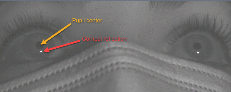
The pupil is defined as the dark region around the center of the pupil. The pupil diameter is measured by mapping this region as an oval, and taking the major axis as the current diameter.
The relationship between the pupil center and corneal reflection changes systematically as a participant looks around the display:
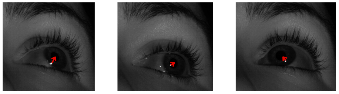
The exact nature of this change depends on several other factors:
-
the angle of the camera/lamp
-
the position of the participant
-
individual morphology of the eye/face
-
which eye is being tracked
Therefore, it is necessary to build a unique model of this change for each participant, and each eye, each time they or the camera take on a new position. This is done by calibrating the eye tracker at the start of the session.
Related links:
After calibration, we can infer with high accuracy and precision where the participants are looking. This allows us to report the x and y gaze position in screen coordinates. This data is collected at a rate of 2000 samples/second. Simple rolling window averages can be configured to generate automated fixation and saccade detection flags during online analysis; more complex analyses can be applied in postprocessing to categorize types of eye movements (e.g., microsaccades).
Tracking loss occurs when the camera loses one or both landmarks. This may be an indication that the participant has looked offscreen or has blinked; the camera cannot distinguish between the two events, but simple heuristics can be used to identify one vs. the other in postprocessing. Tip: blinks are typically preceded by a rapid downward saccade.
TRACKPixx3 data output
The TRACKPixx3 samples data at 2000 Hz. Each sample saves the following information:
|
Col |
Name |
Units |
Description |
|
1 |
Time tag |
seconds |
Time, in seconds, since the control unit was last turned on. Uses the same clock as all other I/O on the control unit for easy synchronization. |
|
2 |
Left Eye x |
pixels |
x screen coordinate, in pixels, corresponding to the calibrated x position of the left eye. Uses a Cartesian system where (0,0) corresponds to the center of the display. |
|
3 |
Left Eye y |
pixels |
y screen coordinate, in pixels, corresponding to the calibrated y position of the left eye. Uses a Cartesian system where (0,0) corresponds to the center of the display. |
|
4 |
Left Eye Pupil Diameter |
pixels |
The diameter of the left pupil. The pupil is mapped as an ellipse; the diameter always reflects the major (longest) axis of this ellipse. |
|
5 |
Right Eye x |
pixels |
x screen coordinate corresponding to the calibrated x position of the right eye. Uses a Cartesian system where (0,0) corresponds to the center of the display. |
|
6 |
Right Eye y |
pixels |
y screen coordinate corresponding to the calibrated y position of the right eye. Uses a Cartesian system where (0,0) corresponds to the center of the display. |
|
7 |
Right Eye Pupil Diameter |
pixels |
The diameter of the right pupil. The pupil is mapped as an ellipse; the diameter always reflects the major (longest) axis of this ellipse. |
|
8 |
Digital Input |
integer |
An integer value which represents the 24-bit digital input to the control unit. This value will change in response to button box presses, incoming triggers, and any other input coming in from the Digital In port. |
|
9 |
Left Eye Blink |
boolean |
0 if the left eye is open, 1 if the left eye is closed. |
|
10 |
Right Eye Blink |
boolean |
0 if the right eye is open, 1 if the right eye is closed. |
|
11 |
Digital Output |
integer |
An integer value which represents the 24-bit digital output being sent from the control unit. This value will change in response to outgoing triggers, e.g. from the DOut schedule or Pixel Mode. |
|
12 |
Left Eye Fixation |
boolean |
Default 0, changes to 1 if the conditions for a left eye fixation event are met. By default, the fixation flag raises when the eye has moved less than 2500 pixels/second for the last 25 consecutive frames. These default thresholds can be changed by the user. |
|
13 |
Right Eye Fixation |
boolean |
Default 0, changes to 1 if the conditions for a right eye fixation event are met. By default, the fixation flag raises when the eye has moved less than 2500 pixels/second for the last 25 consecutive frames. These default thresholds can be changed by the user. |
|
14 |
Left Eye Saccade |
boolean |
Default 0, changes to 1 if the conditions for a left eye saccade are met. By default, the saccade flag raises when the eye has moved more than 10,000 pixels/second for the last 10 consecutive frames. These default thresholds can be changed by the user. |
|
15 |
Right Eye Saccade |
boolean |
Default 0, changes to 1 if the conditions for a right eye saccade are met. By default, the saccade flag raises when the eye has moved more than 10,000 pixels/second for the last 10 consecutive frames. These default thresholds can be changed by the user. |
|
16 |
Message code |
– |
implemented in future release |
|
17 |
Left Eye Raw x |
pixels |
x value of the left eye pupil-corneal vector |
|
18 |
Left Eye Raw y |
pixels |
y value of the left eye pupil-corneal vector |
|
19 |
Right Eye Raw x |
pixels |
x value of the right eye pupil-corneal vector |
|
20 |
Right Eye Raw y |
pixels |
y value of the right eye pupil-corneal vector |
Eye tracking data is stored in a memory buffer on the device. This allows for an extremely high, uninterrupted sampling rate. Data can be accessed in three ways:
-
Access current eye position via API commands or Tracker.gazeX, Tracker.gazeY in Labmaestro.
This method requires a USB transaction to the control unit, which takes time. This method is intended for online experiment management (e.g., gaze-based screen updating). It should not be used for offline analysis. -
Batch import tracking data from the device buffer using API commands or the StopTrackerRecording command component in LabMaestro.
This method is recommended for offline data analysis. The control unit can hold approximately 60 minutes of continuous tracking data; we recommend importing data often (e.g., between experiment blocks) to ensure data is not lost if the experiment crashes. -
Stream eye tracking data to a third party analog receiver (e.g., an MEG acquisition system). This requires a DATAPixx3 control unit and a custom cable. See this guide for details: Configuring the TRACKPixx3 Analog Output.
Below are some general timing guidelines for the three different methods:
|
Method |
Description |
Use Cases |
Time delay from eye movement → acquired data |
|---|---|---|---|
|
Get eye position |
Query current eye position from experiment PC |
Fast checking of eye position during experiment |
~1.95 ms (variable, due to USB transaction) |
|
Batch import buffer data |
Import data from tracker buffer for analysis |
Postprocessing of gaze data |
1.7 ms |
|
Stream data to analog output |
Streaming gaze data to analog receiver (requires DATAPixx3 & analog cable) |
Recording gaze data on external system |
1.7 ms |
It is important to consider this delay in the greater context of your experiment. For instance, if you are running a gaze-contingent display, you also need to consider delays associated with evaluating the gaze position, rendering the image buffer, and passing the rendered image to the display. On a high-performance PC with a 120 Hz monitor and low-demand graphics, an end-to-end latency of 2-3 video frames (16.6-25 ms) is reasonable.
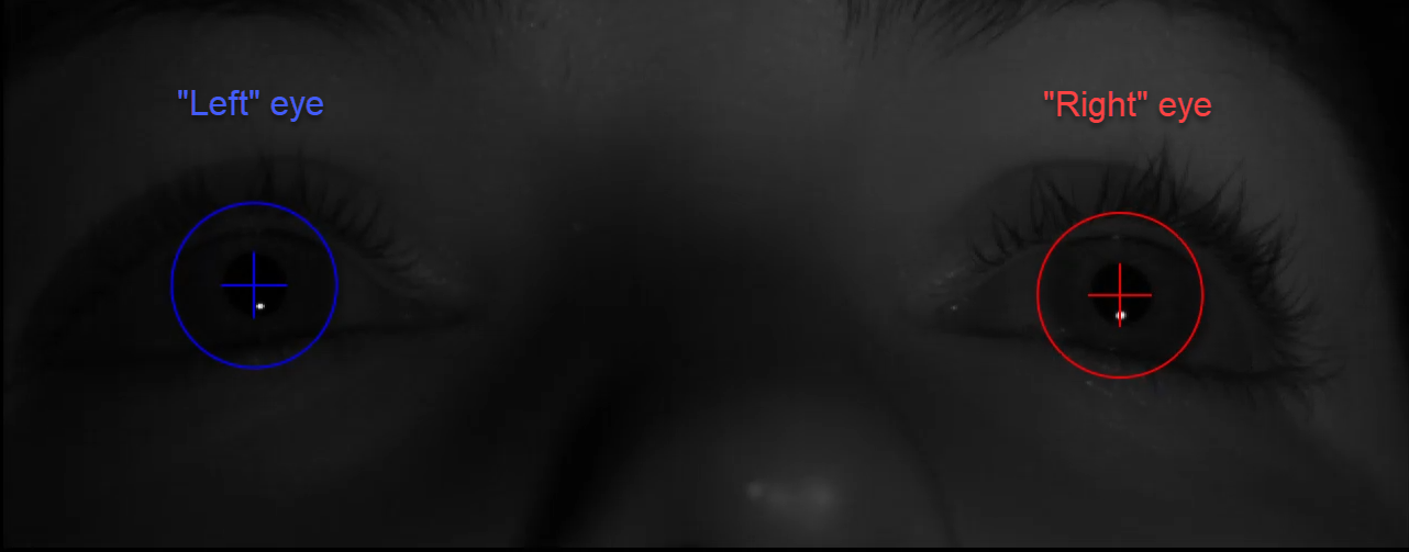
Coordinate systems
In all TRACKPixx3 tools, the directions ‘left’ and ‘right’ always refer to the sides of the camera view as it appears on the display. These labels may not correspond to the left and right eyes from your participant’s point of view.
As mentioned in the table above, x and y screen coordinates are in pixels. They use a convention where the origin (0,0) is in the middle of the screen:
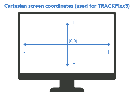
Compare this to screen coordinates for a number of popular psychology software tools, where screen resolution in pixels is W x H:
|
Program |
Location of Origin (0,0) |
(x, y) value of bottom right corner |
How to convert TRACKPixx buffer data (x, y) |
|---|---|---|---|
|
TRACKPixx buffer |
Center |
(W/2, -H/2) |
— |
|
Psychtoolbox |
Top left corner |
(W, H) |
PTBx = x + (W/2);
|
|
PsychoPy (pix, origin=center) |
Center |
(W/2, −H/2) |
PsychoPyx = x;
|
|
PsychoPy (norm, origin=center) |
Center |
(1, −1) |
PsychoPyx = x / (W/2); PsychoPyy = y / (H/2) |
Automatic video and digital input synchronization
Your control unit supports sending video-based digital triggers via Pixel Mode. Some units can also send custom triggers configured by the user (e.g., to indicate audio onset). Outgoing digital signals are automatically recorded by the tracking buffer (see Column 11 in the buffer contents table), allowing you to align eye movement data with stimulus behaviours with excellent precision.
Digital input from button boxes or third party devices is also captured in the tracking buffer (Column 8).
Cleaning and Maintenance
Do not use cleaners that contain any petroleum-based materials such as benzene, thinner, or any other volatile substance to clean any part of this product.
The camera mount, camera body and illuminator body can all be wiped down with commercial cleaner. Cables may also be wiped down. Avoid bending the fibre optic cables; they are very fragile. Sockets can be cleaned out with compressed air.
The glass LED illuminator cover and camera lens can be cleaned with a soft, microfiber cloth and a commercial LCD screen cleaner (like this one). You can also use warm water and a small amount of gentle soap, such as hand soap. Excess soap and water can then be removed with a second clean cloth.
Chinrests should be thoroughly disinfected between uses, as they come in direct contact with your participant’s face. Spray liberally with disinfectant solution and wipe down with a cloth.
Troubleshooting your Device
Having trouble getting good tracking? See Common Eye Tracking Problems and How to Solve Them, or contact our support team to set up a training session over Teams.
Related Links
-
VPixx Online Classroom and Library (VOCAL) articles:
-
Introduction to Eye Tracking with the TRACKPixx3 -
TRACKPixx3 Calibration Walkthrough -
Common Eye Tracking Problems and How to Solve Them -
Implementing a Real-Time Gaze Follower on the Console -
Configuring the TRACKPixx3 Analog Output -
Visualizing Gaze Data -
Checking if Fixation is Inside a Region of Interest
-
-
Book a personalized eye tracking training session with a staff scientist
Compliance, Safety and Warranty Information
Click on the sections below to expand the relevant information.
Compliance Information
The VideoBahn interface on the TRACKPixx3 uses a fiber optic module whose manufacturer provides a certificate of conformance for standard IEC 60825-1 Ed. 3 (2014).
|
CLASS 1 LED DEVICE IEC 60825-1 Ed. 3 (2014) |
|---|
For the United States of America
This device complies with part 15 subpart B of FCC rules. Its operation is subject to the following two conditions: (1) this device may not cause harmful interference, and (2) this device must accept any interference received, including interference that may cause undesired operation. This equipment has been tested and found to comply with the limits for a Class A digital device, pursuant to part 15 subpart B of the FCC rules.
For Canada
This Class A digital apparatus complies with Canadian ICES-003.
CISPR warning: This is a Class A product. In domestic environments this product may cause radio interference in which case the user may be required to take adequate measures.
For European Countries
DECLARATION OF CONFORMITY
|
|
Manufacturer’s Name:
Manufacturer’s Address:
|
Product Name: TRACKPixx3
Part Numbers: VPX-TRK-3410C
Product Options : All
Application of Council Directive:
|
2014/30/EEC
|
Electromagnetic Compatibility directive
|
|
The following harmonized standards have been used: |
|
|
EN 61326-1:2013
|
Electrical equipment for measurement, control and laboratory use.
|
|
|
SUPPLEMENTARY INFORMATION
To remain CE compliant, only CE compliant parts should be used with this product. Maintaining CE compliance also requires proper cable and cabling techniques. VPixx Technologies will not retest systems or components that have been modified by customers. Signature: 
|
The following information is only for EU member states:

|
The mark shown to the left is in compliance with the Waste Electrical and Electronic Equipment directive 2012/19/EU (WEEE). The mark indicates the requirement NOT to dispose of the equipment as unsorted municipal waste. For more information call VPixx Technologies Inc. or email us at support@vpixx.com |
Declaration of RoHS Compliance
|

|
This product has been designed and manufactured in compliance with Directive 2015/863/EU of the European Parliament and the Council on the restriction of the use of certain hazardous substances in electrical and electronic equipment (RoHS Directive). |