
This manual refers to the VIEWPixx /3D and VIEWPixx /EEG calibrated research-grade displays. For details on the discontinued VIEWPixx 12-bit monitor, please see Hardware Manuals for Discontinued Products.
Product Overview
The VIEWPixx series offers research-grade, fully calibrated LCDs designed for vision science labs.
-
Full HD Performance: 1920 × 1080 @ 120 Hz for sharp, precise visuals.
-
Industrial LCD Glass: Durable, high-performance glass ensures clarity and fast response times.
-
Calibrated Uniformity: Factory-calibrated for >95% luminance and >90% color uniformity.
-
Scanning Backlight: Mimics CRT scanning for crisp transitions with minimal ghosting.
-
Digital TTL Triggering: 24-channel TTL output syncs stimuli with microsecond precision.
-
Scientific Display Solution: Optimized for psychophysics and timing-sensitive research.
Currently available models:
-
VIEWPixx /EEG: 8-bit color, plug-and-play design.
-
VIEWPixx /3D: up to 10-bit color, supports analog/digital I/O, console monitor, and 3D display (when paired with 3DPixx shutter glasses).
Product Details
This section includes detailed information about the various ports of the VIEWPixx series. Expand the relevant section to view details about the device subsystem, including technical specifications and pin assignment.
.png?cb=9d6c80c34db2e86461d02218103641c8)
2. Digital output
Digital output
All VIEWPixx models support TTL digital outputs via a DB25 port on the rear of the unit (highlighted below). TTL stands for transistor-transistor logic, which is a simple digital communication protocol that consists of rising and falling voltages. It is commonly used for rapid, simple communication between electronic devices. Common applications in research include sending TTL “triggers” to signal events like visual stimulus onset to third-party systems.
Technical specifications:
-
24 digital outputs on DB25 connector (female)
-
Output drive stage: 5 V through 25 Ω series resistor
-
Maximum output current:
-
Source: 15 mA
-
Sink: 12 mA
-
Detailed pin assignment information:
Below are the industry standard pin labels and their corresponding function. Pins 1-12 are configured for even digital output channels from 0-22; pins 12-25 are configured for odd digital output channels from 1-23; pin 13 is ground. Note that pin numbering follows the industry standard for DB25 ports.
|
Pin |
Description |
Pin |
Description |

|
|
1 |
Digital Out 0 |
14 |
Digital Out 1 |
|
|
2 |
Digital Out 2 |
15 |
Digital Out 3 |
|
|
3 |
Digital Out 4 |
16 |
Digital Out 5 |
|
|
4 |
Digital Out 6 |
17 |
Digital Out 7 |
|
|
5 |
Digital Out 8 |
18 |
Digital Out 9 |
|
|
6 |
Digital Out 10 |
19 |
Digital Out 11 |
|
|
7 |
Digital Out 12 |
20 |
Digital Out 13 |
|
|
8 |
Digital Out 14 |
21 |
Digital Out 15 |
|
|
9 |
Digital Out 16 |
22 |
Digital Out 17 |
|
|
10 |
Digital Out 18 |
23 |
Digital Out 19 |
|
|
11 |
Digital Out 20 |
24 |
Digital Out 21 |
|
|
12 |
Digital Out 22 |
25 |
Digital Out 23 |
|
|
13 |
GND |
Shield * |
||
*Shield is tied to the GND by a 0 Ohm resistor inside the VIEWPixx.
3. Digital input [VIEWPixx /3D ONLY]
Digital input [VIEWPixx /3D ONLY]
The VIEWPixx /3D supports TTL digital inputs via a DB25 port on the rear of the unit (highlighted below).
TTL stands for transistor-transistor logic, which is a simple digital communication protocol that consists of rising and falling voltages. It is commonly used for rapid, simple communication between electronic devices. Typical applications in research include receiving high-speed input from TTL-based button boxes and MRI triggers.
Technical specifications:
-
24 inputs on DB25 connector (female)
-
Input termination: >20 kΩ pull-up to 3.3 V
-
Input tolerance: 5 V
Detailed pin assignment information:
Below are the industry standard pin labels and their corresponding function. Pins 1-12 are configured for even digital input channels from 0-22; pins 12-25 are configured for odd digital input channels from 1-23; pin 13 is ground. Note that pin numbering follows the industry standard for DB25 ports.
|
Pin |
Description |
Pin |
Description |
|
|
1 |
Digital In 0 |
14 |
Digital In 1 |
|
|
2 |
Digital In 2 |
15 |
Digital In 3 |
|
|
3 |
Digital In 4 |
16 |
Digital In 5 |
|
|
4 |
Digital In 6 |
17 |
Digital In 7 |
|
|
5 |
Digital In 8 |
18 |
Digital In 9 |
|
|
6 |
Digital In 10 |
19 |
Digital In 11 |
|
|
7 |
Digital In 12 |
20 |
Digital In 13 |
|
|
8 |
Digital In 14 |
21 |
Digital In 15 |
|
|
9 |
Digital In 16 |
22 |
Digital In 17 |
|
|
10 |
Digital In 18 |
23 |
Digital In 19 |
|
|
11 |
Digital In 20 |
24 |
Digital In 21 |
|
|
12 |
Digital In 22 |
25 |
Digital In 23 |
|
|
13 |
GND |
Shield * |
||
*Shield is tied to the GND by a 0 Ohm resistor inside the VIEWPixx /3D.
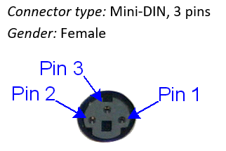
6. VESA 3D interface [VIEWPixx /3D ONLY]
VESA 3D interface [VIEWPixx /3D ONLY]
The VIEWPixx /3D's VESA 3D interface enables 3D stimulus presentation on the screen. A VESA-compliant system like the 3DPixx must be connected to use 3D features.
Detailed pin assignment information:
Below are the industry standard pin labels and their corresponding function.
|
Pin |
Description |
|
|
1 |
+5 VDC ** |
|
|
2 |
GND |
|
|
3 |
VESA_LR (+5 VDC) |
|
|
Shield* |
||
*Shield is tied to the GND by a 0 Ohm resistor inside the VIEWPixx /3D.
**Current limited (400mA).
9. Combined analog input/output [VIEWPixx /3D ONLY]
“Full” vs. “Lite” Systems: As of September 2023, all VPixx data acquisition systems include analog and audio I/O functionality. Units sold before this were either Lite or Full models; only Full models have analog and audio I/O features enabled. Depending on the age and model of your device, you may not have access to these features. For more details, see our FAQ.
Combined analog input/output [VIEWPixx /3D ONLY]
Analog signals are continuous voltages that vary over time and are used to record fluctuating variables like position, force and energy. They are also the foundation for audio output. Modern systems digitize analog signals using Analog to Digital Converters (ADC) and convert digital signals back into analog using Digital to Analog Converters (DAC). The VIEWPixx /3D features 16 ADC channels (or 8 differential channels) and 4 DAC channels on a single DB25 port on the rear of the unit.
Technical specifications:
Analog to digital converter
-
Number of channels: 16 (or 8 differential), on DB-25
-
Converter resolution: 16 bits
-
Maximum sampling rate: 200 kSPS per channel
-
Frequency programming modes:
-
samples per second or per video frame
-
nanoseconds per sample
-
-
Simultaneous sampling across all channels
-
Input range: ±10 V
-
Input impedance: 1.6*108 Ω // 3 pF
-
Absolute maximum input tolerance: ±12 V
Digital to analog converter
-
Number of channels: 4 on DB-25 connector
-
Converter resolution: 16 bits
-
Maximum sampling rate: 1 MSPS per channel
-
Frequency programming modes:
-
samples per second or per video frame
-
nanoseconds per sample
-
-
Simultaneous output updates
-
Output range: ±10 V on 4 ch
-
Drive capability: ±25 mA
Detailed pin assignment information:
Below are the industry-standard pin labels and their corresponding functions. Note that pin numbering follows the industry standard for DB25 ports.
|
Pin |
Description |
Pin |
Description |
|
|
1 |
ADC0 |
14 |
ADC1 |
|
|
2 |
ADC2 |
15 |
ADC3 |
|
|
3 |
ADC4 |
16 |
ADC5 |
|
|
4 |
ADC6 |
17 |
ADC7 |
|
|
5 |
ADC8 |
18 |
ADC9 |
|
|
6 |
ADC10 |
19 |
ADC11 |
|
|
7 |
ADC12 |
20 |
ADC13 |
|
|
8 |
ADC14 |
21 |
ADC15 |
|
|
9 |
REF0 |
22 |
REF1 |
|
|
10 |
GND |
23 |
+5 VDC ** |
|
|
11 |
DAC0 |
24 |
DAC1 |
|
|
12 |
DAC2 |
25 |
DAC3 |
|
|
13 |
GND |
Shield * |
||
*Shield is tied to the GND by a 0 Ohm resistor inside the DATAPixx3.
** Current limited (400mA).
System Requirements
The following section outlines the software and hardware requirements for the PC connected to the VIEWPixx display.
VPixx Software Tools
VPixx Software Tools is a package of APIs and high-level software tools for use with VPixx products. It contains everything you need to connect to, configure and operate our devices from your experiment PC. It includes the following:
-
LabMaestro, a program designed by VPixx Technologies for configuring VPixx hardware and designing/implementing experiments.
-
Datapixx.mex, a library of commands for use with MATLAB/Psychtoolbox and VPixx products
-
pypixxlib, a library of Python tools for VPixx products
The latest version of VPixx Software Tools can be downloaded directly from our website at any time. Support documentation, tutorials, and demos for all of our software tools can be found on our support site: https://docs.vpixx.com/
Supported operating systems
VPixx Software Tools are developed and supported under Windows, macOS and Linux (Ubuntu) operating systems. For an up-to-date list of supported OS versions visit Software Download & Information.
Recommendations for experiment PCs and graphics cards
We regularly receive questions about what experiment PC characteristics and graphics cards we recommend for use with our hardware. Generally speaking, most modern machines and GPUs (i.e., from the last 5 years) should be compatible with our devices. The following minimum video output must be supported:
-
PROPixx projector, VIEWPixx LCD Series: 1920 x 1080 resolution, 120 Hz refresh
-
VIEWPixx3 /OLED: 2560 × 1440 resolution, 120 Hz refresh
Unfortunately, we are not able to exhaustively test commercially available systems and make specific recommendations regarding makes/models.
Recommendations for video adapters
We provide a DisplayPort to Dual Link DVI adapter for your VIEWPixx. Please use one of the following video protocols from your PC:
-
Dual-Link DVI
-
DisplayPort
-
DisplayPort mini/Thunderbolt
-
USB-C to DisplayPort
We do not recommend converting from other video protocols (e.g., HDMI or VGA) as this can have unpredictable consequences for display behaviour. For more details, see FAQ: Can I use a video adapter if my graphics card does not have dual-link DVI output?
Assembly and Installation
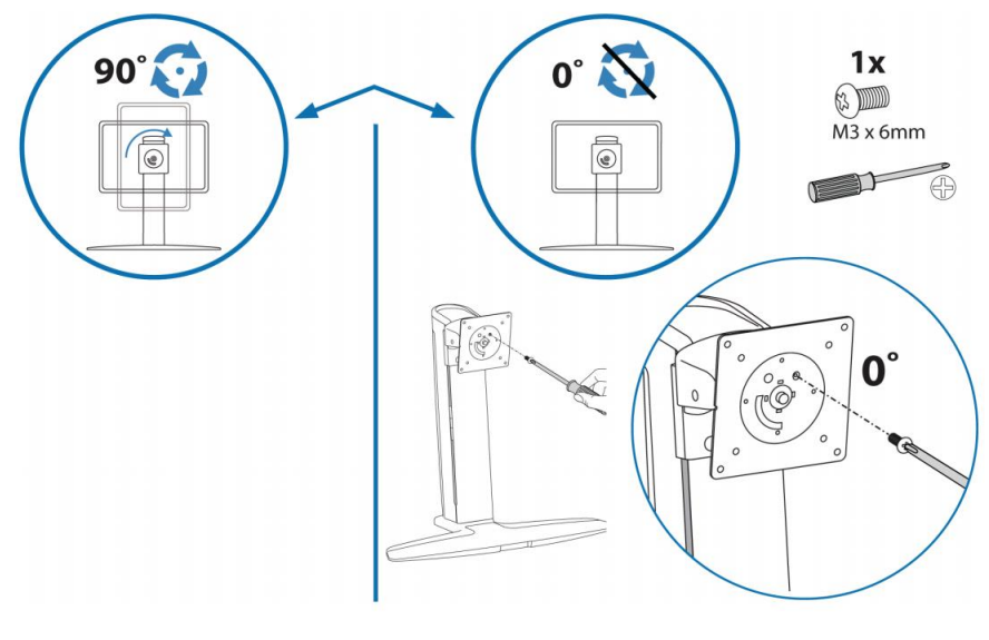
What’s included with your product
-
Monitor
-
Stand for monitor
-
AC adapter and power cord, with international adapter set
-
6-foot USB-B to USB-A cable
-
6-foot DVI-D to DVI-D cable
-
Active DisplayPort to DVI-D adapter
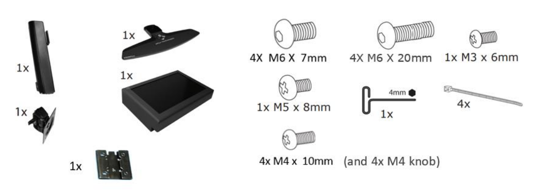
Product assembly - Installing the monitor on the stand
Ensure you have all the provided tools for assembly. You will also need a Phillips head screwdriver ( + )
-
Unpack the VIEWPixx on a flat, soft, and protected surface. To protect the surface, place the monitor screen down for assembly.
-
Attach the base to the stand.
-
Secure the LCD bracket to the stand. Slide the bracket down the sliding rail and use the 4 provided M6 x 7 mm screws to fix it in place. Ensure the grooves are at the top of the bracket.

-
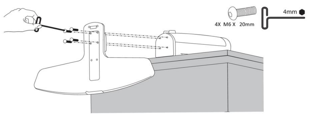
Attach the LCD tilt bracket to the LCD bracket using the provided M5 x 8mm screw and a Phillips screwdriver.

5. (Optional) Prevent rotation with 1x M3 x 6mm screw inserted into the LCD tilt bracket.
6. Secure the monitor using the four provided M4 x 10mm screws or 4x M4 knobs.
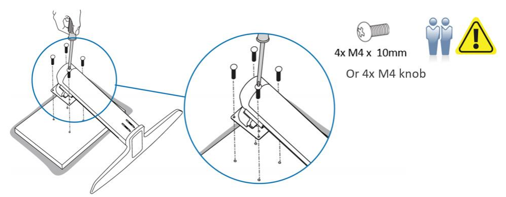
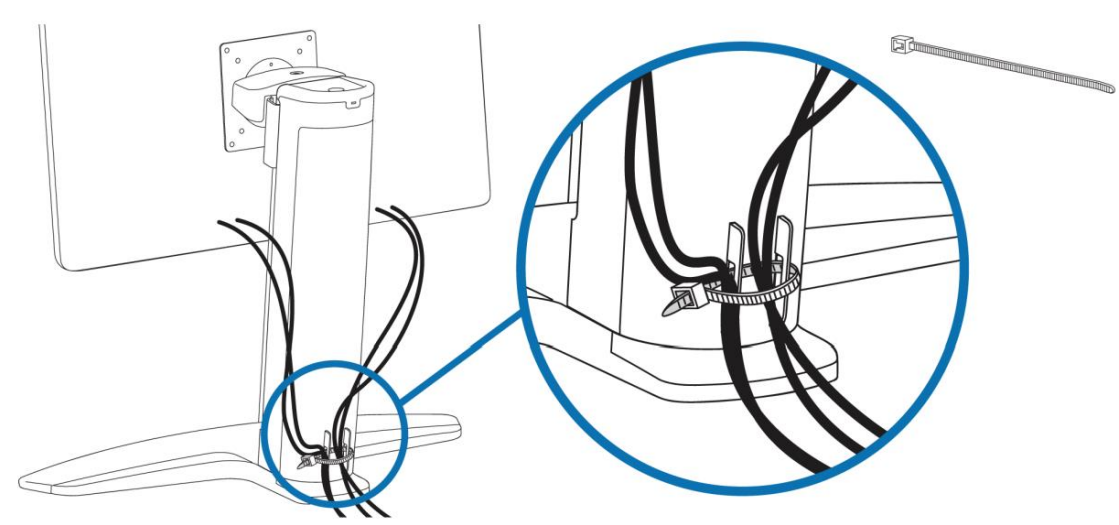
7. Secure cables at the back of the stand (e.g., with a tie wrap)
Product assembly - Connecting the monitor to your PC
Use the cables provided with your order. Do NOT substitute cables of unknown origin. If you require longer cables than what has been provided, contact support@vpixx.com for assistance.
Unlike a traditional LCD, the VIEWPixx has a video connection and a USB connection to the experiment PC. When the monitor is successfully connected, you should detect the VIEWPixx as a connected USB device in your Device Manager and as a display in your system display settings.
-
Connect the VIEWPixx monitor’s 12V power input (#7 in the labelled image in the Product Details section) to a suitable power source using the provided cable and AC adapter.
-
Connect the VIEWPixx monitor USB-B port (#1) to a USB port on your experiment PC.
-
Connect the VIEWPixx monitor DVI In port (#5) to the DisplayPort to DVI adapter provided in your order.
-
Connect the DisplayPort to DVI adapter to a) a suitable DisplayPort adapter on your PC and b) a USB port (this powers the adapter).
-
[Optional - VIEWPixx /3D only] Connect the console monitor to the DVI Out port on the side of the VIEWPixx /3D
.png?cb=585f3e25bb24da93e2a7ea0d2ef1877c)
Product Usage
Warm-up time
Like all LCD-based displays, the VIEWPixx series monitors require a brief ‘warm-up’ period to reach a stable operating temperature. This is critical to ensure optimal display uniformity and consistency. We recommend a warm-up period of at least 20 minutes before conducting any research or taking any measurements.
Test Patterns
Test patterns are simple demonstrations of VPixx products. They are preloaded onto VPixx hardware and do not rely on your graphics card or experiment code. They are used to quickly visualize product features and validate system performance, independent of your PC.
Some VPixx devices have test patterns that can be accessed by remote control. For access to all device test patterns, open the LabMaestro application, right-click on the device in the Environment section of the Project pane, and select Test Patterns from the menu. This will open the Test Pattern widget.
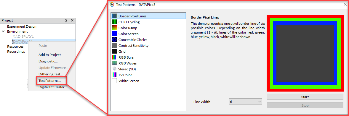
Only test patterns suitable for your selected device will appear in the widget. Each test pattern includes an explanation of the pattern and an example of expected behaviour. Some test patterns include options to adjust the pattern parameters. While a test pattern is enabled, your device will be unresponsive to typical user behaviour (e.g., mouse clicks). Stop the test pattern to return to regular operation.
LabMaestro 1.11 is currently supported under Windows and Linux. MacOS support will be implemented soon. To access test patterns in macOS, open the vputil application and type ‘tp’ to see options.
Pixel Mode
In Pixel Mode, your VPixx hardware sends automated digital TTL signals, aka ‘triggers,’ based on the colour of the top left pixel on the display. Triggers are locked to video frame onset with deterministic timing and microsecond precision. You can learn all about this feature in this guide: Sending Triggers with Pixel Mode. Use our Pixel Mode pixel value calculator to determine what pixel values you should use for your desired TTL output.
3D applications [VIEWPixx /3D only]
This device has a VESA-standard 3D port, which can be used with the 3DPixx active shutter glasses kit (sold separately) to display 3D stimuli at a rate of 60 Hz/eye. There are several video modes available for formatting 3D stimuli with this system; for a comprehensive guide and demos, see this guide:
Analog subsystem [VIEWPixx /3D only]
The analog subsystem of this device supports up to 16 concurrent analog inputs and 4 analog outputs. Analog cable are sold separately. For more details on how to use and configure analog channels on our hardware, see the following guides:
Digital subsystem [VIEWPixx /3D only]
The digital subsystem comprises a 24-channel digital input and a 24-channel digital output. These can be configured for recording and playback of TTL signals, respectively. Common digital inputs include our RESPONSEPixx button boxes and MRI triggers. Common outputs include custom event-based triggers, Pixel Mode triggers, and forwarding of button box inputs to third-party systems. For details on how to use the digital subsystem, including examples, see these guides:
Audio subsystem [VIEWPixx /3D only]
The audio subsystem includes a microphone in, an audio in, and an audio out. This device does not interact with your PC soundcard. Instead, you can configure the device hardware to record mic/audio inputs to the device’s onboard memory for later retrieval, load audio waveforms into device memory for playback with deterministic timing, or both. The advantage of this approach is that the device can operate independently of and in parallel with your experiment PC for improved timing and stimulus synchronization. For more details on how to use the audio system, see the following guides:
Product Specifications
LCD panel characteristics
For a summary of LCD panel characteristics, including resolution, physical size, contrast ratio, pixel pitch and more, see pages 3-4 of our product datasheet [PDF]. This section provides additional details about the VIEWPixx display that are relevant to vision scientists.
Scanning backlight
The VIEWPixx displays are LCD panels equipped with a specialized scanning backlight. Unlike a standard LCD monitor, which has a constant backlight, the scanning backlight illuminates the display row-by-row in a pattern similar to the vertical scanning raster of a CRT.
There are many good reasons to do this from a scientific perspective. You can read more about the design of our monitors here: Why replace a CRT monitor?. The subframe temporal characteristics of pixels, scanning backlight and video-based triggers are explained in detail in this guide: Measuring Pixel Behaviour and Temporal Characteristics of the VIEWPixx /3D.
Display gamma
The gamma characterizes the relationship between the pixel values sent to the display and the output luminance, according to the function L = Vγ , where L is the output luminance, V is the input value of the pixel (typically expressed as a value from 0-1 or 0-255), and γ is the gamma exponent.
Modern LCD panels typically have a gamma of 2 or more, meaning that, in practice, the luminance output of the display does not increase linearly with the input values specified by the user. This has significant consequences for vision science paradigms where stepwise increments of light values are needed.
To correct for the nonlinear relationship between pixel values and output on commercial displays, many researchers perform gamma correction, in which an inverse function is applied to pixel values such that the output is linearized. We have an in-depth tutorial for how to do this here: Gamma-Correct the Luminance of a Display.
In some cases, it is sufficient to supply your experiment software with a single gamma value for your display, and it will automate the correction for you. This approach is less precise than the method linked in our tutorial but should still approximate linear output. If you wish to take this approach, all VIEWPixx series monitors have a gamma close to the industry standard of 2.2. There is some variability across units, but this is a reasonable estimate.
Gamma correction can impact Pixel Identity Passthrough, the 1-1 mapping of pixel value assignment and output. This has consequences for certain features of VPixx hardware, like Pixel Mode. To learn more about Pixel Identity Passthrough, see our guide: What is Pixel Identity Passthrough?
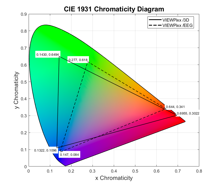
Colour gamut
The colour gamut of a display can be expressed as coordinates in the 1931 CIE colour space. Below are the coordinates of the maximal red, green, and blue outputs of a VIEWPixx /EEG and a VIEWPixx /3D monitor. These are direct measurements of calibrated units in our production line; the exact values of individual units may vary.
The following factors can affect product gamut:
-
Ambient room temperature
-
The operating temperature of the unit (see Warm Up Period above)
-
Age of unit
-
Individual monitor and backlight characteristics
Cleaning and Maintenance
Commercial cleaning products or disinfectants can be used to clean the stand, frame, and cables. Do not apply products directly to the hardware; instead, apply them to a soft cloth and wipe down the hardware as needed.
Ports may be cleaned using compressed air.
We recommend a commercial LCD screen cleaner like this brand to clean the LCD panel. You can also use a damp microfiber cloth and a gentle soap such as hand soap. Do not use cleaning products on the LCD panel. Commercial cleaners and sanitizing products contain harsh solvents which can damage the coating on the panel. Do not apply firm pressure or rub at the panel, which can damage the display.
A sheet of plexiglass or plastic film can protect your display. This second surface may be cleaned and disinfected as needed.
Troubleshooting your Device
|
Issue |
Solution |
|---|---|
|
Display not detected |
Try the following:
|
|
Flashing red square in the top corner |
The screen is operating below the recommended refresh rate of 100 Hz or higher; the timing performance of the display is no longer guaranteed. Change your display settings to use the optimal refresh rate. If no option >60 Hz appears in your display setting options, follow the troubleshooting steps for the issue ‘Display not detected’ |
|
Sudden or intermittent rapid horizontal scrolling of display contents |
DisplayPort to Dual-Link DVI adapter has become desynchronized. Reset the adapter by disconnecting and reconnecting the power to the adapter. |
Related Links
-
VIEWPixx /3D topics:
Compliance, Safety and Warranty Information
Click on the sections below to expand the relevant information.
Compliance Information
For the United States of America
This device complies with part 15 subpart B of FCC rules. Its operation is subject to the following two conditions: (1) this device may not cause harmful interference, and (2) this device must accept any interference received, including interference that may cause undesired operation. This equipment has been tested and found to comply with the limits for a Class A digital device, pursuant to part 15 subpart B of the FCC rules.
For Canada
This Class A digital apparatus complies with Canadian ICES-003.
CISPR warning: This is a Class A product. In domestic environments this product may cause radio interference in which case the user may be required to take adequate measures.
For European Countries
DECLARATION OF CONFORMITY
|
|
Manufacturer’s Name:
Manufacturer’s Address:
|
Product Name: VIEWPixx Full, VIEWPixx Lite, VIEWPixx /3D Full, VIEWPixx /3D Lite, VIEWPixx XL-48 Lite, VIEWPixx XL-48 Full, VIEWPixx /EEG
Part Numbers: VPX-VPX-2001C, VPX-VPX-2000A, VPX-VPX-2005D, VPX-VPX-2004B, VPX-VPX-2010A, VPX-VPX-2011C, VPX-VPX-2006B
Product Options : All
Application of Council Directive:
2014/30/EEC -Electromagnetic Compatibility directive
2015/863/EU -Restriction of Hazardous Substances Directive
2012/19/EU -Waste Electrical and Electronic Equipment directive
|
|
SUPPLEMENTARY INFORMATION
To remain CE compliant, only CE compliant parts should be used with this product. Maintaining CE compliance also requires proper cable and cabling techniques. VPixx Technologies will not retest systems or components that have been modified by customers. Signature: 
|
The following information is only for EU member states:

|
The mark shown to the left is in compliance with the Waste Electrical and Electronic Equipment directive 2012/19/EU (WEEE). The mark indicates the requirement NOT to dispose of the equipment as unsorted municipal waste. For more information call VPixx Technologies Inc. or email us at support@vpixx.com |
Declaration of RoHS Compliance
|

|
This product has been designed and manufactured in compliance with Directive 2015/863/EU of the European Parliament and the Council on the restriction of the use of certain hazardous substances in electrical and electronic equipment (RoHS Directive). |