Introduction
In this introduction, you will learn how to use region and pattern components to draw a white circle on top of a uniform gray background. This tutorial is intended as a first step to understanding how to handle components through the LabMaestro interface.
Prerequisites
-
LabMaestro is installed and activated.
Project Files
Regions_Patterns_StaticPatterns.lm
Tutorial - Create a Gabor Patch by Combining Regions and Patterns
To start, create a new, empty Project in LabMaestro. To do so, open the LabMaestro application and click File -> New (empty). You can save this project through File -> Save.
Creating a Timeline
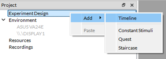
To begin adding components to your project, you must first add a timeline. Right-click on Experiment Design in the Project window, located in the upper-left of the interface by default. Select Add -> Timeline to create a basic empty Timeline with only one Epoch by default.
Part 1 – Create Regions on the Screen
In this demo, we will explore Region components to create a white circle on top of a uniform gray background.
Create a Rectangle Region
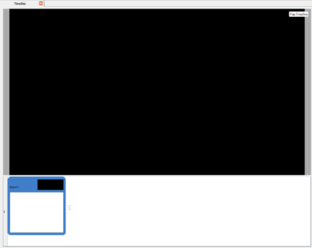
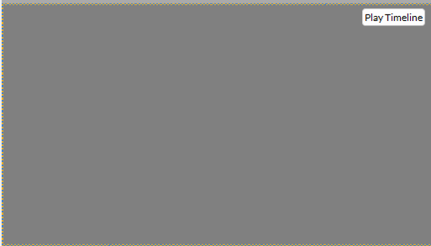
The first step should be to create the background region. As a first step, go into the Component Library (by default, on the lower left of your screen). Under Regions, drag & drop a Rectangle into your Epoch. Your screen should now look like this:
As you can see, we have added a rectangular region to our project. However, we must resize it to cover the full screen, which we can do by modifying our Rectangle's properties in the "Properties" tab (by default, to the right of the interface).
Region Properties
The Properties menu should look like this:
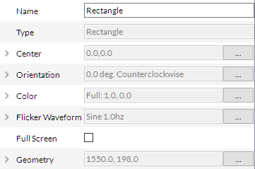
You can read more details about each property on the Regions page in the LabMaestro documentation. As a quick refresher, here is what each property can do:
-
Center: Specify the position of the region's center relative to the experiment display.
-
Orientation: Specify the region's orientation in degrees.
-
Colour: Specify the region's colour.
-
Flicker Waveform: Enables and controls region flicker.
-
Geometry: The region size on the screen.
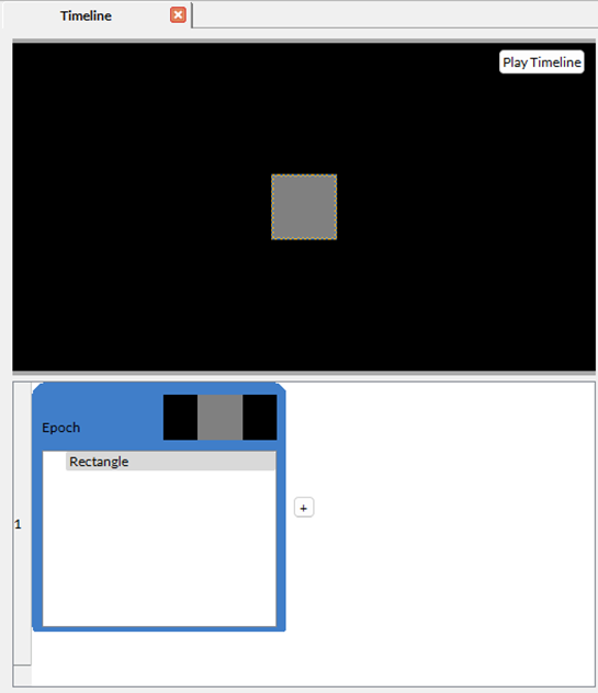
To keep this region as the background, we can toggle Full Screen, which turns off the Geometry property (since the region’s size will match your display's resolution).
Your timeline preview should now look like this:
More recent versions of the LabMaestro Experiment builder also allow you to define the background colour from the Timeline properties.
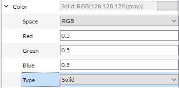
By default, the rectangle colour is gray. If you want to define specific RGB values, use the Solid type and enter each RGB value. 0.5 in all channels will return a uniform gray background.
Create a Circular Region on top of the Background
Now that our background is properly defined, we can add a circular region on top of the background. In the Component Library, under Regions, drag and drop an Oval in your Epoch.
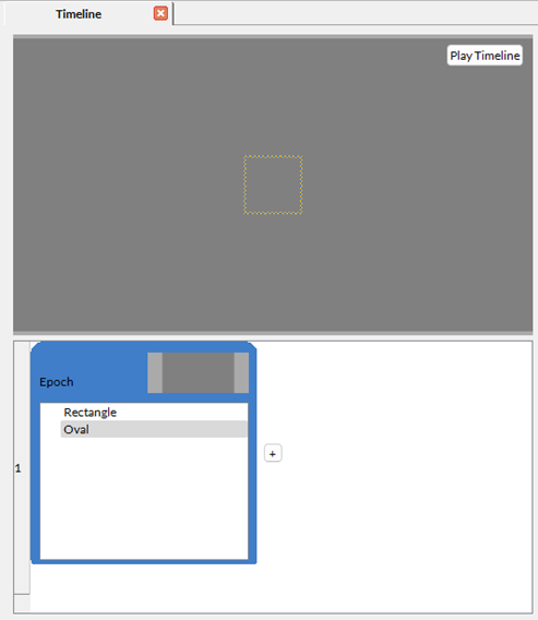
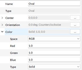
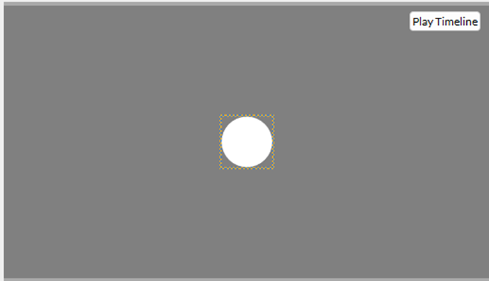
The outline in the timeline preview indicates that the new region was added. However, it is not visible as the oval is the same colour as the background. To remedy this, we must adjust the colour properties of the new Oval region. We set it to white.
Once this is defined, your timeline preview should now look like this:
To better understand the effect of different region properties, please take some time to experiment with different values in each of the “Oval” region's properties. Refer to Regions to read on the effect of each property.
Part 2 – Use Patterns to Display a Circular Grating
Following the previous part, let us learn how to add a pattern to a specific region on the screen.
Add a Grating Inside the Oval Region
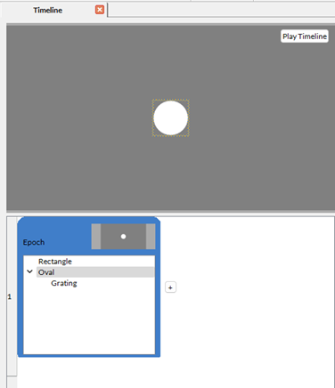
To add a pattern to a region, drag & drop a pattern into the region name in the Epoch. To add a grating, open the Component Library, select Patterns, and then Grating. Drag & drop this component over the Oval region defined previously. Your timeline preview should now look like this:
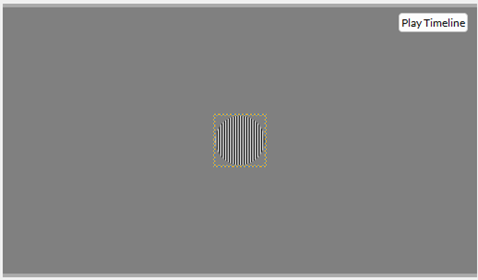
The grating component was successfully added to the Epoch; however, it is not visible in the preview. To change this, we must set the Oval object's Colour property to Full.
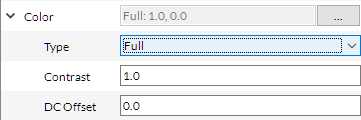
Your timeline preview should now look like this:
Change Pattern Properties
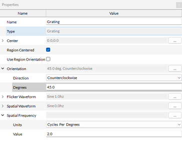
As with the Oval region in the part, we can now change the Grating object's properties to modify its appearance. You can edit properties from the Properties panel. As an example, let us change the Grating's Orientation and Spatial Frequency. We can apply a 45-degree counterclockwise rotation, and change the Spatial Frequency to 2 cycles per degree:
Your grating should now look like this in your timeline preview:
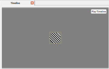
Because we defined this grating's spatial frequency in degrees of Visual angle, it may appear differently on your LabMaestro instance depending on your display settings. See this page for more information.
Part 3 – Use Combine Mode to Create a Gabor Patch
You can also combine LabMaestro patterns to create more complex visual stimuli. In this part, we will combine the previously created grating with a Gaussian pattern to create a Gabor patch.
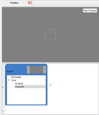
As a first step, let us add a Gaussian pattern to our timeline. To do so, look at the Component Library, under Patterns, and choose Gaussian. Drag & drop this pattern over the Oval region in your Epoch. Your timeline preview should now look like this:
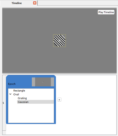
As you can see, the Gaussian was automatically added on top of the grating component. However, this is not the outcome we want. To change this, open the Properties panel when selecting the Gaussian pattern; you will see a new property named Combine Mode.
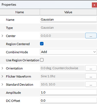
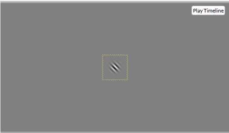
To create a Gabor Patch, we choose the Multiply Combine Mode. Once this is changed, your timeline preview should look like this:
We now have a proper Gabor patch, but it's small. We can change this by editing the Gaussian component's Standard Deviation property. For instance, by setting it to .4 degrees of visual angle for both height and width, we obtain:
There are many more possible uses of Combine Modes. For instance, combining two Gratings of different orientations using the Multiply combine mode can create plaids, like so:
Other Visual Stimuli
A second timeline in this template includes other sample visual stimuli:

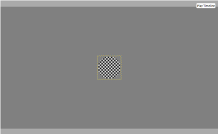
Checkerboard: Shows a Checkerboard Pattern whose square sizes are adjusted by Expressions so that there are always 10 squares per row.
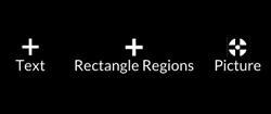
Fixation Crosses: Demonstrates three different ways to draw fixation crosses. The first is a cross made by writing a + sign in a Text Region. It is quick and easy, and its appearance is modified using standard font options (font family, size, etc.). The second fixation cross is a cross formed by superimposing shapes using the Rectangle Region. Its appearance is highly customizable, but the number of required regions increases with the shape's complexity. The third fixation cross is made by applying a Picture Pattern to a small rectangular region. The fixation cross picture was created in Adobe Photoshop and exported as a PNG.
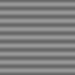
Horizontal Sinewave: A low-frequency horizontal grating with a sinusoidal waveform, made with a Grating Pattern.
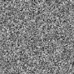
Gaussian Noise: Often used to implement visual masking, implemented with a Noise Pattern.
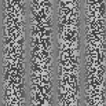
Contrast Modulated Sine Wave on Noise Texture Carrier: A stimulus characterized by changes in contrast over space rather than a change in luminance. Made by multiplying a Grating Pattern with a Noise Pattern through the Multiply Combine Mode.
Part 4 – Using a Custom Resource as a Pattern
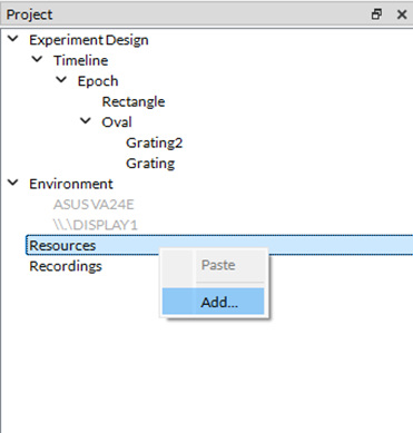
Should your experiments require more complex or "real-world" visual stimuli (e.g., Faces), LabMaestro allows users to import custom resources as patterns. You can do this from the Project panel by right-clicking Resources and selecting Add.
You can then browse your file explorer to import your resource into the project. The resource will then appear greyed out (while unused) under the Resource section of the project window. As a good practice, we recommend keeping your resources in the same folder structure as the LabMaestro project.
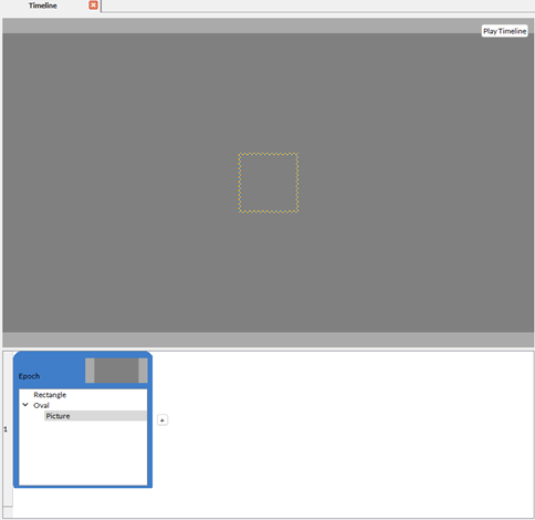
To use this resource in a project, you can use the Picture component. Add this component to the previously created Oval region. To do so, look in the Component Library, under Patterns, and drag & drop the Picture component on top of the Oval region. Here is what the timeline preview will look like:
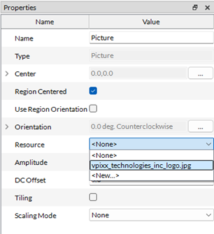
We must now specify which resource we will be using in the Picture component's properties. Set the Resource property to the image you previously imported to the project:
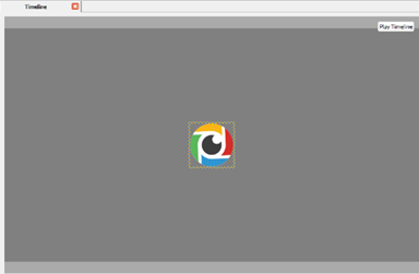
Once this is done, your timeline preview should now look like this:
If you are using video stimuli, you can replace the Picture component with the Movie component. You can import videos into the LabMaestro project the same way you import images.
Related Links
Components: Building Blocks of Experiments
Customizing Stimuli with Mathematical Functions and Expressions